13
SLC440COM Series
SLG440COM Series
Operating instructions
Safety light curtain / safety light grid
EN
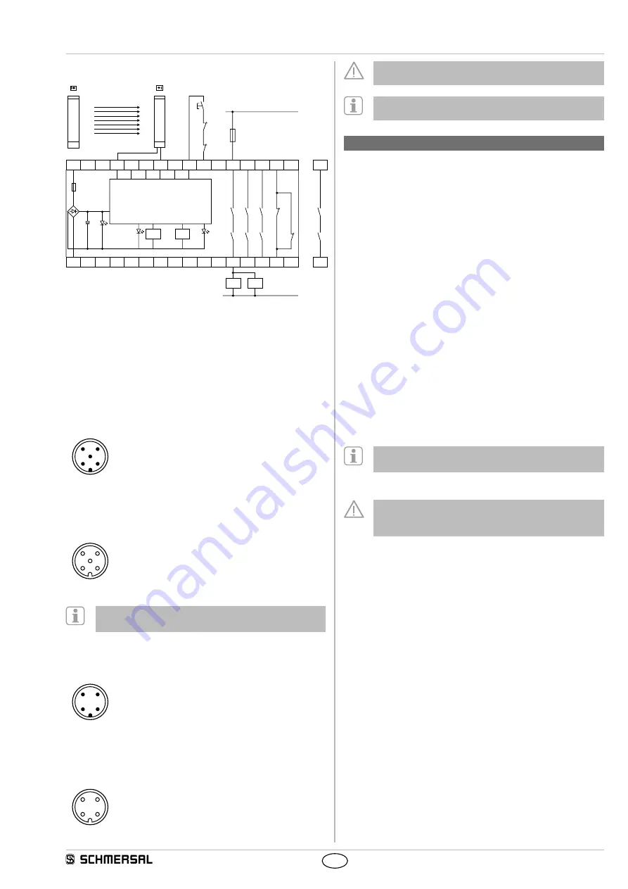
5.2 Wiring example with safety relay module
A2
A1
S12 S11 S21 S22
X1 X2
13
L1
33 41
23
K2
K1
Ui
K2
K1
F1
Ansteuerlogik/
Logic
14 24 34 42
N
S
J
K
A
K
B
K
A
K
B
K
B
K
A
Safety relay module
• Contactor control K
a
and K
b
at X1/X2
• Command device
J
Restart interlock restart at X1/X2
• OSSD outputs at S12 and S22
• QS-switch = nQS, deactivate cross-wire short detection
5.3 Connector configuration Receiver, Emitter & Cable
RECEIVER
SLC Connector
M12, 5-pole
Designation
Description
3
2
5
1
4
1 BN 24 VDC
power supply
2 WH OSSD 1
Safety output 1
3 BU 0 VDC
power supply
4 BK OSSD 2
Safety output 2
5 GY Release/restart
interlock
Acknowledgement restart
interlock
Cable: Connector
female
M12, 5-pole
3
2
5
1
4
It is possible to use the Automatic operating mode with a
4-pole cable (without pin 5 restart interlock)
EMITTER
SLC Connector
M12, 4-pole
Designation
Description
3
2
1
4
1 BN 24 VDC
power supply
2 WH Not used
Do not connect a signal
(do not wire)
3 BU 0 VDC
power supply
4 BK Not used
Do not connect a signal
(do not wire)
Cable: Connector
female
M12, 4-pole
3
2
1
4
The colour codes are only valid for the cable types mentioned
below "optional accessories"
For UL evaluated products we do recommend to use the UL
style cable 20549
6. Set-up and maintenance
6.1 Check before start-up
Prior to start-up, the following items must be checked by the
responsible person
Wiring check prior to start-up
1 The voltage supply is a 24V direct current power supply (see
technical specifications), which meets the CE Directives, Low Voltage
Directives A power downtime of 20 ms must be bridged
2 Presence of a voltage supply with correct polarity at the AOPD
3 The connecting cable of the emitter is correctly connected to
the emitter and the connecting cable of the receiver is correctly
connected to the receiver
4 The double insulation between the light curtain output and an
external potential is guaranteed
5. The outputs OSSD1 and OSSD2 are not connected to +24 VDC.
6 The connected switching elements (load) are not connected to
+24 VDC.
7 If two or more AOPD are used within close range compared to each
other, an alternating arrangement must be observed Any mutual
interference of the systems must be prevented
Switch on the AOPD and check the operation in the following way:
The component performs a system test during approx 2 seconds after
the operating voltage has been switched on After that, the outputs are
enabled if the protection field is not interrupted The status indication at
the receiver is on
In case of incorrect functionality, please follow the instructions
listed in the chapter Fault diagnostic
6.2 Maintenance
Do not use the AOPD before the next inspection is
terminated An incorrect inspection can lead to serious and
mortal injuries
Conditions
For safety reasons, all inspection results must be archived The
operating principle of the AOPD and the machine must be known in
order to be able conducting an inspection If the fitter, the planning
technician and the operator are different persons, please make sure
that the user has the necessary information at his disposal to be able
conduct the maintenance
6.3 Regular check
A regular visual inspection and functional test, including the following
steps, is to be performed:
1 The component does not have any visible damages
2 The optics cover is not scratched or soiled
3 Hazardous machinery parts can only be accessed by passing
through the protection field of the AOPD
4 The staff remains within the detection area, when works are
conducted on hazardous machinery parts
5 The safety distance of the application exceeds the mathematically
calculated one


