3
CSS 30S
CSS 300
Operating instructions
Safety sensor
EN
Rated impulse withstand voltage U
imp
:
0.8 kV
Rated insulation voltage U
i
:
32 V
Response time:
< 60 ms
Duration of risk:
< 60 ms
Safety outputs Y1/Y2:
NO function, dual-channel,
p-type, short-circuit proof
Rated operating voltage U
e1
:
24 VDC (-15% / +10%)
Voltage drop:
U
e
< 1 V
Leakage current l
r
:
< 0.5 mA
Related operating current l
e1
:
max. 0.25 A
Minimum operating current I
m
:
0.5 mA
Utilisation category:
DC-12, DC-13
Required rated short-circuit current:
100 A
Diagnostic output:
short-circuit proof, p-type
Rated operating voltage U
e2
:
24 VDC (-15% / +10%)
Voltage drop:
U
e
< 5 V
Related operating current l
e2
:
max. 0.05 A
Utilisation category:
DC-12, DC-13
Serial diagnostic
Operating current:
150 mA, short-circuit proof
Wiring capacitance for serial diagnostics:
max. 50 nF
2.6 Safety classification
Standards:
ISO 13849-1, IEC 61508
PL:
e
Control Category:
4
PFH:
3.6 x 10
-9
/ h
PFD:
3.95 x 10
-5
SIL:
suitable for SIL 3 applications
Service life:
20 years
3. Mounting
3.1 General mounting instructions
During fitting of the actuator and the sensor, the requirements
of ISO 14119, especially paragraph 7 must be observed!
The sensor enclosure must not be used as an end stop. The component
can be mounted in any position. The active surface of the safety sensor
and the actuator have to be opposite. The safety sensor must only be
used within the assured switching distances ≤ sao and ≥ sar.
The safety sensor and the corresponding actuator can be fixed using
the supplied M30 nuts (A/F 36). The max. tightening torque is 30 Nm
(CSS 30S) or 400 Ncm (CSS 300).
A concealed mounting is possible, however this reduces the switching
distance. The reduction will be lower, when the sensor and the actuator
protrudes a few mm.
The actuator has a slot in the active front surface. In confined spaces,
this slot can be used to fix the actuator by means of a screwdriver.
Safety sensor and actuator must be permanently fitted to the
safety guards and protected against displacement by suitable
measures (tamperproof screws, gluing, drilling of the screw
heads).
To avoid any interference inherent to this kind of system and any
reduction of the switching distances, please observe the following
guidelines:
• Minimum distance between two sensors:
CSS 30S: 50 mm
CSS 300: 100 mm
• The presence of metal chips in the vicinity of the
sensor is liable to modify the switching distance
• Keep away from metal chips
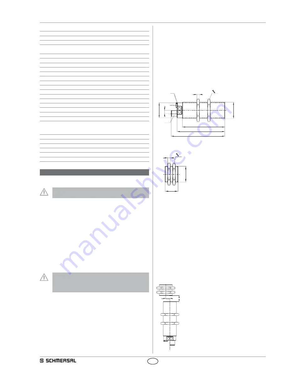
3.2 Dimensions
All measurements in mm.
Safety sensor
M3
0
x
1,5
78,5
99,5
88,5
6
5
Ø28
LED
M12 x 1
36
Actuator
24,5
M30x1,5
5
36
3.3 Adjustment
The LED of the safety sensor can be used as an adjustment tool.
The yellow flashing LED of a sensor signals that an adjustment of the
switching distance is required. Reduce the distance between the sensor
and the actuator, until the LED of the safety sensor is continuously lit
yellow.
The correct functionality of both safety channels must be checked by
means of the connected safety-monitoring module.
3.4 Switching distance
The graphs show the switch-on and switch-off points of the sensor
due to the approach of the actuator. The maximum misalignment of
the actuator with regard to the sensor centre is 9 mm. A concealed
mounting of the sensor and the actuator will reduce the switching
distance. (see “Mounting” part)
S
V


