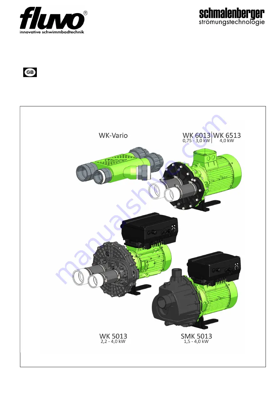
Centrifugal pump
Type WK/SMK
Operating / Assembly manual
Translation of the original
Entwurf 27.10.2020
27
22
0
- E
Страница 1: ...Centrifugal pump Type WK SMK Operating Assembly manual Translation of the original Entwurf 27 10 2020 27220 E ...
Страница 2: ...001 2023999999 has been manufactured in accordance with the following directives Directive 2006 42 EC Machinery Harmonised standards that were used EN 809 1998 A1 2009 AC 2010 EN ISO 12100 2010 EN 60034 1 2010 EN 60034 5 2001 A1 2007 EN 60034 30 1 2014 EN 61800 3 2018 Authorised representative for the compilation of the technical documentation Robin Krauß Quality assurance Schmalenberger GmbH Co K...
Страница 3: ... the Device 10 3 Transport Storage and Assembly 11 3 1 Transport and Storage 11 3 2 Unpacking Cleaning and Assembly 12 3 3 Setting up and Connecting 13 3 4 Connecting the Pipelines 13 4 Electrical Connection 16 4 1 Electrical Connection General 16 4 2 Elec trical Connection Pump Type WK 16 5 Device Units 18 5 1 Pump Kit Type WK 18 6 Assembly 18 6 1 Assembly General 18 6 2 Assembly of the Control B...
Страница 4: ...tling the Pump 28 10 Appendix 29 10 1 Decommissioning Placing in Storage Preservation 29 10 2 Disposal 30 10 3 Important Information 30 11 Spare parts 31 11 1 Explosion Drawing type WK5013 31 11 2 Explosion Drawing type WK6013 32 11 3 Explosion Drawing type WK6513 33 11 4 Explosion Drawing type WK6013 Vario 34 11 5 Explosion Drawing type SMK 5013 35 ...
Страница 5: ... consulted regarding adjustments for a new intended use We will be pleased to determine what adjustments would be required for the new intended use Proper use also includes observing the Operator s Manual Residual risk The centrifugal pump system is built according to the state of the art and recognised safety engineering rules Nevertheless danger to life and limb of the operator or third parties ...
Страница 6: ...2 Suction end DN65 G2 Sound level db A 66 Weight kg 38 45 FU Rated values of motor Speed min 1 2 900 Nominal current A 5 6 Voltage V 230 400Y 230Δ 690Y 400Δ Frequenz Hz 50 Output kW 2 2 3 0 4 0 Limit values of the pump Pressure P max bar 1 6 1 9 2 1 Flow rate Q max m h 60 70 Typ 1 Alternating current WK 5013 2 2 2 WS 1 WK 5013 2 3 0 WK 5013 2 4 0 10 WK5013 Bearing carriers ...
Страница 7: ...f motor Speed min 1 2 900 Nominal current A 1 7 2 95 2 86 4 95 9 5 3 6 6 25 11 5 5 75 I max 6 6 Y400V 10 4 3 7 5 I max 8 5 Δ 400V Voltage V 400Y 230Δ 400Y 230Δ 230 400Y 230Δ 230 230 400Y 230Δ 690Y 400Δ Frequenz Hz 50 Output kW 0 75 1 5 1 5 1 9 1 9 2 2 3 0 4 0 Limit values of the pump Pressure P max bar 1 0 1 2 1 2 1 4 1 4 1 9 2 0 Flow rate Q max m h 24 42 42 48 48 60 96 Typ 1 Alternating current W...
Страница 8: ... 45 FU 39 5 46 5 FU Rated values of motor Speed min 1 2 900 Nominal current A 2 86 4 95 9 5 3 6 6 25 11 5 5 75 I max 6 6 Y400V 10 4 3 7 5 I max 8 5 Δ 400V Voltage V 400Y 230Δ 230 400Y 230Δ 230 400Y 230Δ 690Y 400Δ Frequenz Hz 50 Output kW 1 5 1 5 1 9 1 9 3 0 4 0 Limit values of the pump Pressure P max bar 1 2 1 2 1 4 1 4 2 0 2 1 Flow rate Q max m h 42 42 48 48 58 62 Typ 1 Alternating current SMK 50...
Страница 9: ... s Manual through corresponding notices The use of symbols is designed to direct your attention at these notices Caution Risk of injury Risk of damage This symbol warns you of dangers due to mechanical effects Caution Danger of death This symbol warns you of dangers due to electrical current Notices placed directly on the pump such as the arrow for direction of rotation must always be observed and...
Страница 10: ...afety Instructions for Maintenance and Repair Only persons with training as a mechanic and corresponding knowledge are permitted to perform maintenance and repair work on the pump If liquids are pumped that can cause effects detrimental to health in any way suitable measures must be taken rinsing cleaning washing to bring the wetted surfaces of the pump to a condition to ensure handling does not e...
Страница 11: ...g devices which are in perfect working order and have adequate load bearing capacity Never work or stand under suspended loads 3 1 2 Storage Temporary storage Even for temporary storage of short duration store in a dry well ventilated location free of vibration on wooden supports at a temperature that is as constant as possible Unsuitable storage If storage conditions are unsuitable for example hi...
Страница 12: ...provided for protection against transport damage or corrosion Find out which ones have been selected for your centrifugal pump 1 Cover plates on the connections 2 Shaft protection for delivery without motor 3 Protective paint on bare metal parts Before set up or installation of the centrifugal pump these protective devices must be removed No contamination can be allowed to remain inside the pump I...
Страница 13: ...mp Except for the special design pumps are always placed on a base plate with the pump or motor mount and fastened with bolts For assembly on a foundation the centrifugal pump must be aligned with a spirit level 3 4 Connecting the Pipelines Caution The centrifugal pump must never under any circumstances be used as a point for securing the pipeline No forces or moments for example caused by warping...
Страница 14: ...en assembling and disassembling the pipelines be careful with the threaded connections It must be ensured that only suitable composite screw connections are used cylindrical thread Do not use sealing tapes sealing cords hemp or pastes to seal the threaded connections but use liquid pipe or thread sealant We recommended using liquid sealants such as Weicon AN 305 72 or Loctite 5331 3 4 2 Pipelines ...
Страница 15: ...impeller and a mechanical seal The pump is suitable for clean and slightly contaminated liquids Suction lifts up to 2 5m are possible The pump has to befilled with liquid once before the first pump start After the pump is started the air from the suction pipe will be completely pumped away The air disappears in the discharges pipes i e the pump can only vent through the open discharge pipes ...
Страница 16: ...or shaft stub The direction of rotation of the pump is anti clockwise as standard viewed from the suction flange Always note the arrow on the pump indicating the direction of rotation 4 2 Elec trical Connection Pump Type WK Connect the motor according to the circuit diagram in fig 3 Delta connection or fig 4 Star connection Make certain The mains power connection must only be made via a fixed conn...
Страница 17: ...or star delta connection 3 sec 4 2 3 Direction of Rotation Check The direction of rotation of the motor must agree with the direction of the rotation arrow on the motor housing of the pump Check by switching on and off in quick succession If the direction of rotation is incorrect reverse any two phases L1 L2 or L3 of the mains power supply line in the motor terminal box 4 2 4 Auxiliary Equipment f...
Страница 18: ... included in the scope of delivery The pump kit is always the same regardless of the type of pool Fig 5 Pump kit WK The control box must always be positioned above the water level of the pool When setting up the pump there must be sufficient ventilation motor cooling and an adequate possibility for leakage water to flow off 6 Assembly 6 1 Assembly General A min 100 mm B 160 mm S Screw Mount the su...
Страница 19: ...e control box as close as possible to the installation kit Connect the switching tube onto the nipple in the protection cover Caution Do not kink the switching tube and keep it as short as possible maximum length 8 m Connection information for Control box refer to the corresponding operating instructions 27248 Fig 7 Control Box ...
Страница 20: ...em illustration 6 4 Flow Losses Pipes and Elements Water 48 m h turbulent flow roughess value 0 1 mm Flow losses in the pipeline pressure and suction side must be noted Flow losses must be kept low in the components that are used Sample flow values are listed in Fig 9 Non return valve To hydro massage or Water Curtain WK vario Suction unit Water regulation Air regulation To counter current To hydr...
Страница 21: ...ssure loss Flow speed DN 80 0 263 bar 2 562 m s DN 100 0 095 bar 1 718 m s DN 150 0 014 ba 0 812 m s DN 80 Pressure loss Flow speed 45 Bogen 0 015 bar 2 562 m s 90 Bogen 0 006 bar 2 562 m s DN 80 Pressure loss Flow speed Sprungartige Rohrverengung DN 80 auf DN 50 0 278 bar 2 562 m s Kantiger Einlauf unter Winkel 0 027 bar 2 562 m s Fig 9 ...
Страница 22: ...uns easily bserve the instructions in chapter 3 2 3 Assembly 6 The direction of motion has been checked 7 1 1 Starting the Pump The pump must only be turned on with the pressure end shut off element half open and the suction end shut off element completely open Do not open it until full speed is reached Then slowly open it and adjust control to the operating point 7 2 Operation 7 2 1 Operation Mon...
Страница 23: ...the maximum permissible room temperature of 40 C is not exceeded the ball bearing temperature does not exceed 50 C above room temperature or in any case 90 C measured on the outside of the motor housing when the centrifugal pump is in operation the shut off element is not closed in the supply line Chapter 8 Troubleshooting contains a table with the most frequent flow faults their causes and recomm...
Страница 24: ...in accordance with accident prevention requirements UVV and must be performed by qualified specialists 8 1 Type WK Malfunction Possible Remedy 1 Pump runs very loud and produces little output Wrong direction of rotation for the motor Reverse the polarity of the motor in the terminal box thereby switching the direction of rotation Motor fan scrapes against the fan hood Correctly secure the fan hood...
Страница 25: ...ing operation unscrew the air valve and replace if necessary Note The air valve must be positioned above the water level For troubleshooting with type WKN see the Pump Control Operator s Manual 27122 8 2 Typ SMK Malfunction Possible reason Remedy 1 Pump does not prime Wrong drection of rotation The pump has not been filled with liquid nicht richtige Drehzahl der Pumpe Air in the suction pipe Block...
Страница 26: ... bearings Impeller runs against the casing Check frequency converter settings throttle the pump Replace Adjust properly 6 Pump leaking Faulty mechanical seal Faulty gasket Pump casing leaking Replace all seals Replace 9 Maintenance Repair 9 1 Generel Information The operator must ensure that all inspection maintenance and repair work on the pump are performed only by authorised and specially train...
Страница 27: ...sstunden durchgeführt werden Wird die Gleitringdichtung im Rahmen einer Anlagenrevision ausgebaut soll sie durch eine neue ersetzt werden 9 2 1 Lubrication and Change of Lubricant Pumps of type WK WKN and SMK in standard design have bearings only in the drive motor The bearings are designed to last for life and have permanent grease lubrication that cannot be relubricated Faulty bearings must be r...
Страница 28: ...n screws 11 11 5 Unclamp the motor Disassemble any additional connections that are present Loosen the pressure and suction connections Loosen the pump from the base plate Lift the pump completely 9 4 Die sassembly Dismantling the Pump Before beginning Do not begin working until you have checked to ensure that all necessary spare parts are present and they match the pump or the version of the pump ...
Страница 29: ... remove the pump take the measures listed in chapter 9 Maintenance Repair Before the pump is placed in storage it must be thoroughly cleaned and preserved The pump must be preserved inside and out For winter shutdown remove the transmitter radio signal housing and store it at room temperature 10 1 3 Recommissioning after Being Placed in Storage Removal of preservation Before the pump that was in s...
Страница 30: ...and take it out of operation observe local regulations for disposal of industrial waste 10 3 Important Information 10 3 1 Factory Repair 1 If you send the pump in to the manufacturer s plant for repairs or modifications include exact information about the medium pumped by the pump safety sheet 2 Only completely emptied and cleaned pumps are accepted for repair 10 3 2 Ordering Spare Parts When orde...
Страница 31: ...Pump type WK SMK Version 27220 E Schmalenberger GmbH Co KG D 72072 Tübingen Germany 31 11 Spare parts 11 1 Explosion Drawing type WK5013 Fig 11 exemplary presentation WK 5013 088 00 ...
Страница 32: ...Operating Assembly manual 32 Schmalenberger GmbH Co KG D 72072 Tübingen Germany Pump type WK SMK Version 27220 E 11 2 Explosion Drawing type WK6013 Fig 12 exemplary presentation WP 6013 088 00 ...
Страница 33: ...Pump type WK SMK Version 27220 E Schmalenberger GmbH Co KG D 72072 Tübingen Germany 33 11 3 Explosion Drawing type WK6513 Fig 13 exemplary presentation WK 6513 088 00 ...
Страница 34: ...Operating Assembly manual 34 Schmalenberger GmbH Co KG D 72072 Tübingen Germany Pump type WK SMK Version 27220 E 11 4 Explosion Drawing type WK6013 Vario Fig 14 exemplary presentation WP 6013 088 01 ...
Страница 35: ...Pump type WK SMK Version 27220 E Schmalenberger GmbH Co KG D 72072 Tübingen Germany 35 11 5 Explosion Drawing type SMK 5013 Fig 15 exemplary presentation SMK 5013 088 00 ...
Страница 36: ...0 7071 70 08 10 Fax www fluvo de info schmalenberger de Im Schelmen 9 11 D 72072 Tübingen Germany 2020 Schmalenberger GmbH Co KG All Rights reserved This Document is subject to change without notice Pump type WK SMK 27220 E ...