3
PS902 setup and testing
4
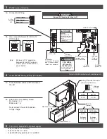
Install 900-BB battery backup (If Included)
DC Output
(Red LED)
900-FA
Connector
12/24 VDC
Output
Terminals
Fire Alarm Jumper
Remove when
900-FA installed
F1
AC Input
(Green LED)
AC Monitor
Active when AC present
and F1 fuse not open
(Form C dry contacts)
24
12
NC C NO
900-BB Connector
High Voltage
If main board must be
removed, turn off AC power
and wait 8 minutes before
removal
Do not remove this cover, no
serviceable parts
DANGER
!
3a
NEU
LINE
Green (Ground)
White (Neutral)
Black (Hot)
AC (In)
120/240
VAC
AC Input
OR
12 VDC
Output Setting
24 VDC
Output Setting
Batter
y 1 Batter
y 2
Black Wires = (-)
+
+
BB LED
(Amber)
On-Solid
AC On
Batteries
Charging
On-Blinking
AC Off
Batteries
Supplying
Power
Battery Supervision Terminals
(Form C Dry Contacts)
Active
AC On
Inactive
AC Off
(Shown
AC Off)
NO
C
NC
Red Wires = (+)
5
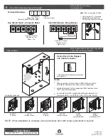
Turn on AC breaker to test power supply
• Verify AC LED is On = GREEN
• Verify DC LED is On = RED
• Verify BB LED (if applicable) is On = AMBER
Minimum of 1/4” separation
between AC and DC wiring as
well as power limited and non-
power limited.
Note:
Refer to 900-BB instructions for additional info
3a Connect AC Wiring
3b Use Jumper to Select 24 VDC or 12
VDC Output
4a Place Batteries in Box with Terminals to
the left
4b Attach Wire from Battery Board
Red wires = (+)
Black wire = (-)
Note: allow 24 hours for batteries
to fully charge
DANGER
If AC LED is
off, turn AC
breaker prior
to checking F1
fuse
DANGER
Ensure AC breaker is turned off


