13
Classic
Pro
HEIGHT OF CUT
Make all adjustments with the engine shut off, spark
plug wire disconnected and mower drive disengaged.
The cutting height is determined by the position of
the blades in relation to the wheels. Variation to this
height may be made at TWO points. (See HEIGHT
OF CUT CHART on page 12.)
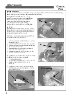
1. THE AXLE POSITION
1. Support the rear of the unit with jackstands
or other suitable means.
2. Remove brake rod
R
from bellcrank
Q
.
3. Remove (4) bolts
M
, (2) washers
K
and
(4) nuts
L
.
4. Place the axle
J
in the desired position
according to the Height of Cut Chart on page
12.
5. Install the bolts, washers and nuts removed
in step 3.
NOTE:
Install the washers
K
on the bolts in the slots.
6. Install the brake rod
R
onto bellcrank
Q
.
7. Adjust brakes and belt guide
V
as shown in
the ADJUSTMENT section.
2. THE CASTER WHEELS
1. Remove the quick pin
P
from the top of the
caster wheel pivot spindle.
2. Place required spacers above or below
wheel support bracket and replace the quick
pin
P
.
Содержание BOB-CAT 33007J
Страница 5: ...5 Classic Pro LABELS ...
Страница 29: ...PARTS SECTION ...
Страница 42: ...42 Classic Pro FIGURE 7 PEERLESS TRANSMISSION ...
Страница 44: ...44 Classic Pro 32 DECK 40 46 45 10 22 20 47 31 40 44 31 40 48 FIGURE 8 ...
Страница 46: ...46 Classic Pro FIGURE 9 36 DECK 47 48 40 10 20 39 44 22 31 40 49 ...
Страница 48: ...48 Classic Pro FIGURE 10 48 DECK 51 50 54 43 45 42 48 53 46 54 44 46 55 55 46 10 20 56 52 22 31 46 57 ...
Страница 50: ...50 Classic Pro FIGURE 11 CASTER ASSEMBLY 1 2 3 4 5 4 6 3 7 8 10 9 15 14 14 11 13 12 16 11 19 18 20 17 ...
Страница 54: ...54 Classic Pro FIGURE 13 DECALS 8 4 UNDER COVER 1 12 11 7 2 10 14 6 9 15 16 13 5 3 ...
Страница 56: ...56 Classic Pro FIGURE 14 CUTTERDECK WEIGHTS ...


