Schenker XMG A722 Скачать руководство пользователя страница 19

Disassembly

Removing the Hard Disk Drive 2 - 9

2.Disassembly

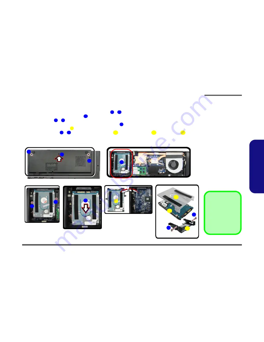
Removing the Hard Disk(s) in the Secondary HDD Bay

1.

Turn 

off

 the computer, and turn it over and remove the battery.

2.

Locate the component bay cover and remove screws 

 - 

 and the cover.

3.

The hard disk will be visible at point 

 on the mainboard


(

Figure 5b

)

.

4.

Remove screws 

 - 


(

Figure 5c

)

.

5.

Grip the tab and slide the hard disk in the direction of arrow 


(

Figure 5d

).

6.

Lift the hard disk assembly 

 out of the compartment


(

Figure 5e

)

.

7.

Remove the screws 

 - 

 to release the hard disk(s) 

 and hard disk mylar 


from the case 

.

8.

Reverse the process to install any new hard disk(s).

Figure 5

Secondary HDD 

Assembly Removal

a. Remove the screws and

cover.

b. Locate the hard disk.
c. Remove the screws.
d. Slide the HDD out.
e. Lift the hard disk assem-

bly out off the computer.

f.

Remove the screws and
separate the HDD(s)
from case.

1

3

4

5

6

7

8

9

10

11

12

13

1

a.

3

b.

c.

2

5

4

8

c.

e.

d.

9

12

13

7

11

f.

6

10

8

Hard Disk Assembly

11. Hard Disks
12. Hard Disk Mylar
13. Hard Disk Case

5  Screws

Содержание XMG A722

Страница 1: ......

Страница 2: ...down properly and don t forget to save your work Remember to periodically save your data as data may be lost if the battery is depleted Do not expose the computer to any shock or vibration Do not plac...

Страница 3: ...pose If you do not have access to a compatible outlet have a qualified electrician install one When you want to unplug the power cord be sure to disconnect it by the plug head not by its wire Make sur...

Страница 4: ...r hands or metal objects Battery Guidelines The following can also apply to any backup batteries you may have If you do not use the battery for an extended period then remove the battery from the comp...

Страница 5: ...43 94cm HD FHD LCD Security BIOS Password Security Kensington Type Lock Slot Audio High Definition Audio Compliant Interface THX TruStudio Pro 2 Built In Speakers Built In Microphone Memory Three 204...

Страница 6: ...ooth 4 0 Factory Option Intel Centrino Wireless N 2230 Wireless LAN 802 11b g n Bluetooth 4 0 Factory Option Third Party Wireless LAN 802 11b g n Factory Option Third Party Wireless LAN 802 11b g n Bl...

Страница 7: ...troduction External Locator Front View with LCD Panel Open Figure 1 Top View 1 Optional Built In PC Camera 2 LCD 3 GPU Button 4 LED Status Indicators 5 Power Button 6 Hot Key Buttons 7 Speakers 8 Keyb...

Страница 8: ...Views 1 5 1 Introduction External Locator Front Right side Views Figure 2 Front Views 1 LED Indicators Figure 3 Right Side Views 1 Multi in 1 Card Reader 2 USB 3 0 Ports 3 Combined eSATA USB 3 0 Port...

Страница 9: ...ocator Left Side Rear View Figure 4 Left Side View 1 Security Lock Slot 2 USB 2 0 Port 3 S PDIF Out Jack 4 Microphone In Jack 5 Headphone Out Jack 6 Optical Device Drive Bay 7 Emergency Eject Hole 1 2...

Страница 10: ...roduction External Locator Bottom View Figure 6 Bottom View 1 Component Bay Cover 2 Vent 3 Battery 4 HDD Bay Overheating To prevent your com puter from overheating make sure nothing blocks the vent fa...

Страница 11: ...ing the connection make sure the connector is oriented in the same way The pin1 side is usually not indicated Pressure sockets for multi wire connectors To release this connector type grasp it at its...

Страница 12: ...pull on the wire 6 Peripherals Turn off and detach any peripherals 7 Beware of static discharge ICs such as the CPU and main support chips are vulnerable to static electricity Before handling any part...

Страница 13: ...turn it over 2 Slide the latch in the direction of the arrow 3 Slide the latch in the direction of the arrow and battery will pop up 4 Lift the battery up Figure b and out of the battery bay 3 Batter...

Страница 14: ...move the battery page 2 5 and remove the component bay cover page 2 5 2 Remove the screw and use a screwdriver to carefully push out the optical device at point 3 Reverse the process to install the ne...

Страница 15: ...computer and turn it over and remove the battery page 2 5 2 Locate the Hard disk bay cover and remove screw 3 Slide the cover at point in the direction of the arrow as illustrated until the case mark...

Страница 16: ...ws 7 Separate the hard disk and hard disk mylar 8 Reverse the process to install a new hard disk s 4 Hard Disk Assembly 7 Hard Disks 8 Hard Disk Mylar 2 Screws Figure 4 HDD Assembly Removal cont d c L...

Страница 17: ...wing pages are all 9 5mm H hard disk drives In some cases 7mm H hard disk drives will be installed Figure 5 Foam Rubber Insert for 7mm H HDDs If you are replacing a 9 5mm H HDD with a 7mm H HDD then i...

Страница 18: ......

Страница 19: ...Figure 5d 6 Lift the hard disk assembly out of the compartment Figure 5e 7 Remove the screws to release the hard disk s and hard disk mylar from the case 8 Reverse the process to install any new hard...

Страница 20: ...primary memory sockets under the component bay cover Primary System Memory Upgrade Process 1 Turn off the computer turn it over and remove the battery page 2 5 and remove the component bay cover page...

Страница 21: ...ent will allow it to only fit one way Make sure the module is seated as far into the slot as it will go DO NOT FORCE the module it should fit without much pressure 11 Press the module in and down towa...

Отзывы: