background image

14 


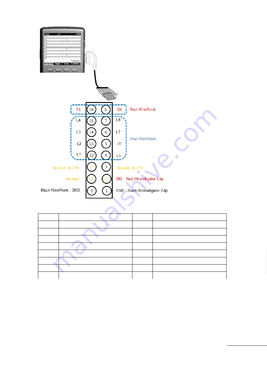
Logic, Pattern, Protocol, Signal Out  - 13    Pin    Cable Connection 


Voltage Warning 

 User should pay attention at the Voltage Rating and Over Voltage warning. 

 Immediately  remove  the  Test  Lead/Test  Probe  from  the  METER  when  VOLTAGE 

WARNING comes on. 

Scope function Input (model SBS-700), max 300V

.   

Other Multi-meter function Input (models SBS-600, SBS-700 ), max 600V. 

Pin No 

Function 

Pin No 

Function 

Ground(Black/Clip) 

Ground(Black/Hook) 

Signal out(Red/Clip) 

10 

N/A 

N/A(pin cutting) 

11 

N/A(pin cutting) 

Logic5(Blue/Hook) 

12 

Logic1(Blue/Hook) 

Logic6(Blue/Hook) 

13 

Logic2(Blue/Hook) 

Logic7(Blue/Hook) 

14 

Logic3(Blue/Hook) 

Logic8(Blue/Hook) 

15 

Logic4(Blue/Hook) 

Pattern Generator RX(Red/Hook) 

16 

Pattern Generator TX(Red/Hook) 

Содержание SBS-600

Страница 1: ...Multi Function Oscilloscope Quick Start Guide Quick start guide will explain basic information about the unit For complete Operation and Safety Information Please refer to the 99 Washington Street Mel...

Страница 2: ...rect Current or Voltage AC Alternating Current or Voltage DC and AC Earth Ground Double Insulation Power Supply OFF Power Supply ON Warning of Electric Shock Warning of Danger Category 1000V Overload...

Страница 3: ...ttery Warning Symbol is blinking on the display the measurement may display in error Recharge the battery or replace Observe all terminal ratings Observe all rating and marking oin the Meter Refer to...

Страница 4: ...al and Electronic Equipment 2002 96 EC Meter complies with WEEE 2002 96 EC requirements Do not dispose Electric Electronics device with other trash Front View Key Pad The Keys are different by models...

Страница 5: ...ly select the Function or Menu Voltage measurement keys AC DC DC AC Current measurement keys AC DC DC AC Resistance Continuity Diode Check key Capacitance measurement key Auxiliary measurements Temper...

Страница 6: ...To return to Auto measurement mode hold key down longer than 2 seconds Upper Line Short Key One Touch press enter Data Logger mode Lower Line Long key Hold longer than 2 seconds to enter Save Data an...

Страница 7: ...tection selection ON OFF 8 V Position Volt Vertical Axis Position adjustment 9 T Position Time Horizontal Axis Position adjustment 10 Trig Level Trigger Level adjustment I Help Short Key One Touch pre...

Страница 8: ...ar Graph refer details Bar Graph page 7 Compare with a reference value and display the Difference 8 Negative Reading 9 Input Over Voltage warning that exceeds the defined safety protection voltage 10...

Страница 9: ...le Q ty in Data Logger 5 Maximum Display Range 6 Minimum Maximum Average of the Samples 7 Total Time Scale of Data Logging 8 Present Measurement Value 9 Change the Time Scale left right horizontal axi...

Страница 10: ...DMX512 1 Wire 2 Time div Measurement Time div Indicator 3 Channels Displays all the Input Channels 4 Horizontal Time Division Position adjustment 5 Trigger Trigger Mode Source and Trigger Level adjus...

Страница 11: ...6 Message Used for making the format cycle and data of each pattern 7 Output Selection of signal out or not 8 Information Display window to show the information of In Out Transaction or all the memori...

Страница 12: ...AX and is displayed at RIGHT of BAR GRAPH at positive MAX Measurement Status display Status icon is displayed at top of Display Battery status Present Measurement Value Buzzer Continuity Data Hold Aut...

Страница 13: ...OM Negative Terminal to all measurements SCOPE V Sig out Volts Continuity Resistance Diode Capacitance Frequency measurement and AUX auxiliary function with external adapter Temperature High Current R...

Страница 14: ...Input model SBS 700 max 300V Other Multi meter function Input models SBS 600 SBS 700 max 600V Pin No Function Pin No Function 1 Ground Black Clip 9 Ground Black Hook 2 Signal out Red Clip 10 N A 3 N...

Страница 15: ...the unit will automatically power off after 15 minutes without a button push User can select the Auto Power Off time min 5 minutes max 2 hours or Auto Power Off mode NOTE Auto Power Off mode is not ac...

Страница 16: ...h press each step Up Down MENU After main function DSO is selected press MAIN Menu to select Channel Trigger Measure Cursor After Main Menu selected Select Sub Menu F1 F2 F3 F4 to proceed to desired m...

Страница 17: ...rer Connect the Battery with the proper polarity When charging the battery use only the AC Adapter and Internal charger supplied from the original manufacturer Please follow Battery Charging procedure...

Отзывы: