


SawStop
®
10” Industrial Cabinet Saw 35
Using Y
our
Saw
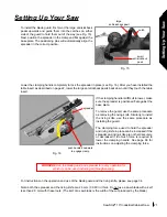
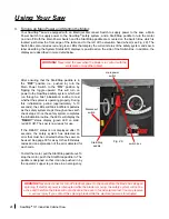
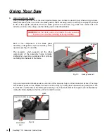
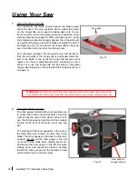
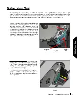
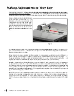
The limit rod blocks material that is taller than
the blade to prevent the material from getting
pinched between the table and the spreader.
The limit rod can be pivoted upward to a balance
point above the guard to provide unimpeded
access to the table opening when changing the
blade, etc. When lowering the limit rod, make
sure to push it down until it snaps into its locked
position (see Fig. 35).
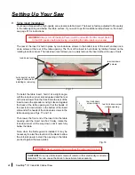
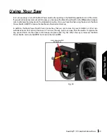
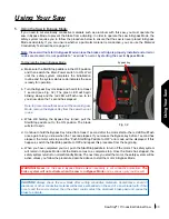
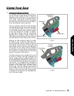
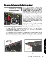
The blade guard shell is constructed of a strong clear polycarbonate to provide a physical barrier between you
and the blade without obstructing your view of the workpiece. The guard shell is designed to capture the air
flow generated by the spinning blade and direct it through a channel above the blade. As a result, virtually all
of the above-table dust created during cutting is collected by the blade guard shell and exhausted through the
port at the back of the blade guard assembly (see Fig. 36).
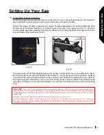
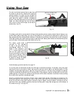
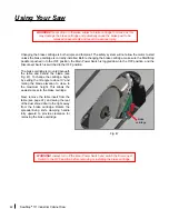
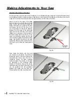
The blade guard shell is
mounted to the spreader
so that it can pivot freely to
automatically adjust to the
height of the workpiece (up
to 3
1
/
8
inches high). Like the
limit rod, the guard shell can
be pivoted upward to a balance
point where it will stay without
further support. This allows you
to adjust or change the blade
without removing the guard.
Install the blade guard as described on page 20.
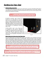
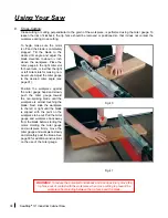
To use the guard, set the blade elevation and tilt angle to the desired settings. If necessary, swing the guard
shell down to rest on the table or insert, and lower the limit rod until it snaps in its locked position. Cut the
workpiece as described beginning on page 38. The guard will “float” on the top of the workpiece as it passes
under the guard. After making the cut, the cut-off portion of the workpiece may be held beneath one of the anti-
kickback pawls. In this case, turn off the motor and wait until the blade completes coast-down before pushing
the cut-off portion past the anti-kickback pawls.
Keep the guard shell clean and free of dust to allow unobstructed viewing of the blade and workpiece. For
successful operation, the spreader must remain flat, and the guard shell and anti-kickback pawls must pivot
freely. If any portion of the guard ceases to function properly, replace or repair it before continuing to use the
saw. When not in use, the blade guard can be stored on the guard / riving knife storage pin on the left side of
the cabinet (see Fig. 3 on page 14).
Using Your Saw
push limit rod down until
it snaps in place
Fig. 35
Fig. 36


