background image

【How to Replacement of Fan Motor】

1. Remove the door. 
   (【How to Replace Cooling Unit】 STEP.1)

2. Remove the motor cover. 
   (【How to Replace Cooling Unit】 STEP.2)

3. Remove the case cover assy. 
   (【How to Replace Cooling Unit】 STEP.4)

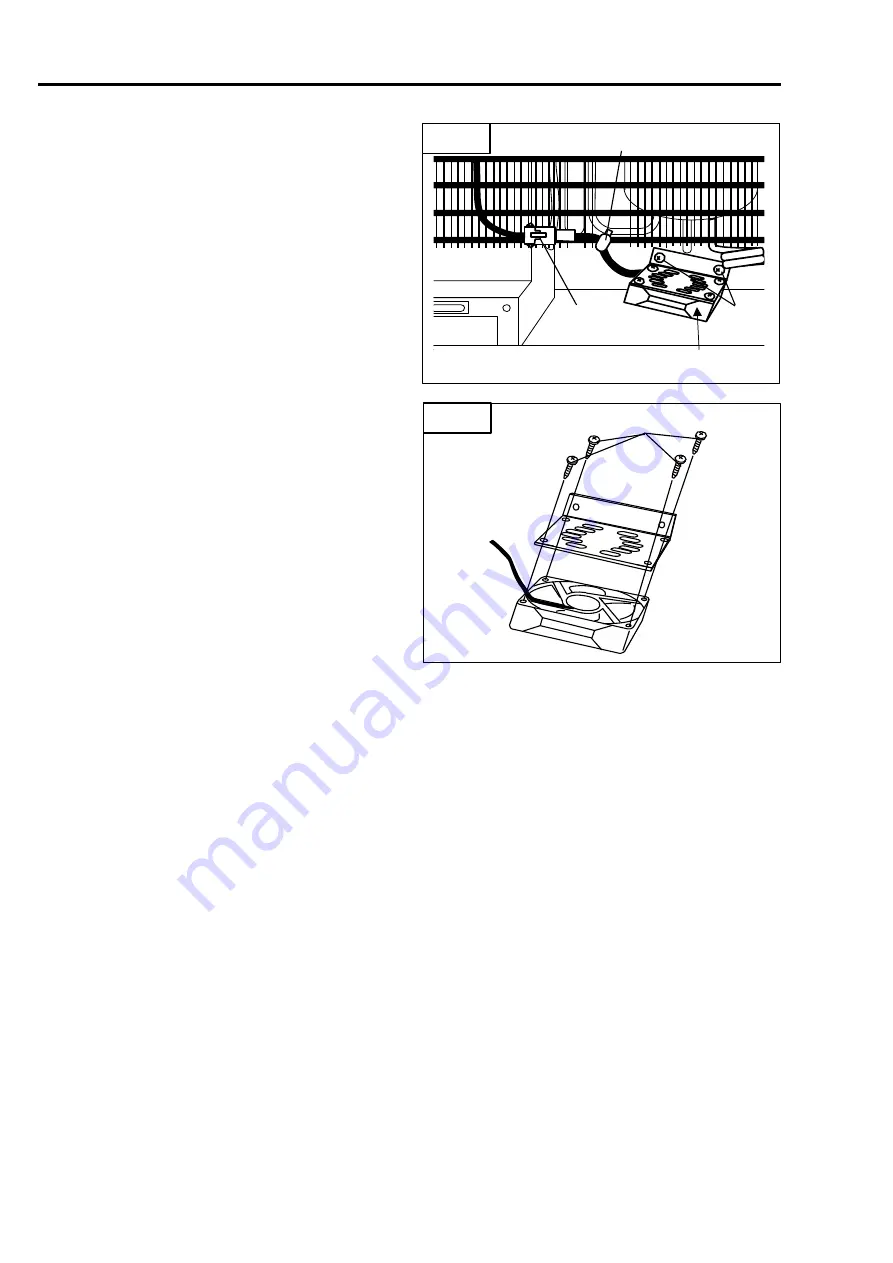
4. Pull out the coupler. (Fig.12-①)

5. Cut fastener. (Fig.12-②)

6. Remove two screws. (Fig.12-③) 

7. Remove four screws. (Fig.12-④) 

7. REPLACING PARTS 

16

Fig.12

Fig.13

FAN MOTOR

Содержание 0642 032 0R12

Страница 1: ...MODEL Type without digital display MT35F U1 0642 032 0R12 MT45F U1 0642 042 0R22 2020 12 1 SERVICE MANUAL ...

Страница 2: ...are familiar with basics service skills and knowledge for ENGEL refrigerator This manual does not guarantee correct maintenance when service is done by a non skilled worker without technical knowledge Note that the content of this booklet including product specifications is subject to change for improvement without notice Always comply with the procedures directions and work tips in this booklet w...

Страница 3: ...eak 7 Refrigerator is too Cold 8 Typical Problem 9 Technical Data 9 6 CHECK POINT CHECK METHOD 10 Check 1 Special Fuse Blade Fuse 10 Check 2 Output Voltage of the Compressor 10 Check 3 Check the Resistance at the Coil if Compressor 10 Check 4 Resistance of Thermistor 11 Check 5 Resistance of Control Assy 11 Check 6 Compressor Rated Current 11 Check 7 Resistance of Thermistor 12 7 REPLACING PARTS 1...

Страница 4: ...HT COMPRESSOR RATING TEMPERATURE CONTROL 1 SPECIFICATIONS OUTER ENCLOSURE COMPRESSOR MODEL INTERIOR DIMENSIONS W H D 1 2 5A EXTERIOR DIMENSIONS W H D 1 MODEL CODE HEAT INSULATOR Painted steel plate Foamed Polyurethane Cyclopentane INNER ENCLOSURE A B S Resin 364 408 648 10 6 10 6 15 270 270 380 MT35F U1 0642 032 0R12 32 14 3 16 1 25 5 46 3 21 MT45F U1 0642 042 0R22 42 14 3 20 25 5 364 508 648 10 6...

Страница 5: ... Tolerance is omitted Unit mm MT35F MT45F 1 SPECIFICATIONS 2 270 408 648 364 648 364 508 380 270 370 380 270 498 MD45F XL Only ...

Страница 6: ...both under fridge or bottom and above fridge top cover Temperature Setting Turn the temperature setting knob to change the air temperature inside the refrigerator 5 3 Vent opening size must be larger than 160 for each opening the more air circulation over the condenser the more efficiently fridge will operate Inside temperature OFF Stop Approx 18 at an ambient temperature of 30 with the refrigerat...

Страница 7: ... MT35F MT45F 3 PART NAME 4 ...

Страница 8: ... Block Diagram MODEL MT35F U1 MT45F U1 Wiring Diagram MODEL MT35F U1 MT45F U1 5 4 CONNECTING DIAGRAM ...

Страница 9: ...ply Replace the cooling unit Resistance of the thermistor Approx 2kΩ 10kΩ 2 Thermistor is broken Ω Replace the thermistor Power supply output voltage Approx AC13V 17V 1 AC 0V Power supply is broken Replace the power supply Lower than AC13V Output maladjustment See page11 Check 4 Output maladjustment See page 10 Check 2 Is temperature control assembly lamp lit Normal Repeats fuse blown Yes Yes No N...

Страница 10: ...r supply output voltage Approx AC13V 17V 1 Lower than AC11V Replace the power supply Output maladjustment Is the fan motor running NO Fan motor is broken Replace the fan motor YES Higher than 2 0A The compressor is locked or contaminated Lower than 1 5A Gas is leaking Compressor rated current Approx 1 5A 2 0A Replace the cooling system Replace the registor variable 0Ω Registor variable is shorted ...

Страница 11: ...assy Approx 5kΩ 17kΩ Dial position 5 OFF Resistance value changes in the dial position Power supply is broken Replace the power supply See page 11 Check 5 Resistance of the thermistor Approx 2kΩ 10kΩ 2 Thermistor is broken Ω Replace the thermistor Control assy is broken Normal Normal Refrigerator is too Cold Can not be temperature adjustment See page11 Check 4 ...

Страница 12: ...f the compressor is open Replace the cooling unit Power supply is broken Replace power supply Compressor does not work Make at least 150mm room between unit and wall Too many things are put inside Lamp of control assy is not lit The special fuse inside DC cord is open Fuse in the vehicle is open Socket or other DC power line in the vehicle is bad Cooling is weak Gas is leaking from Cooling Unit Re...

Страница 13: ...esult Judge Approx AC13 17V Normal AC 0 V Power Supply is broken Approx AC13V or lower Compressor is locked Check 3 Check the Resistance at the Coil if Compressor Fig 3 Checking points Remove two pin coupler at motor cord and check Test result Judge Approx 1 69 Ω Normal Ω Broken 0Ω Coil of compressor is short circuit 6 CHECK POINT CHECK METHOD 10 Please attach attention to the special fuse of orie...

Страница 14: ...t Fig 6 Checking point Test result Judge Approx 1 5 2 0A Normal Lower than 1 5A Gas is leaking Higher than 2 0A Compressor is locked or contaminated Assessment 6 CHECK POINT CHECK METHOD 11 Check the resistance at between terminals brown and black Current value measurement with clamp meter between input cord terminals POWER SUPPLY CONTROL ASSY WORK TIPS When short circuit motor runs continuously F...

Страница 15: ... motor directly can check by connecting the DC24V directly Fig 7 12 6 CHECK POINT CHECK METHOD Fig 7 Please be careful not to mistake the polarity of the power supply When connect with DC24V or wrong polarity fan motor will fail Please use such as support coupler so as not to short circuit power ...

Страница 16: ...ut four couplers Fig 3 Pull out coupler LED LIGHT MT35F 45F TH G4 S Only Fig 3 Take out the power supply Fig 3 7 REPLACING PARTS 13 Fig 2 Fig 3 DOOR Fig 1 14mm 14mm WORK TIPS When re installing for door and hinges please be care with placing position of hinge height Position must be 14mm from the cabinet Please see reference picture in below After installation of door please make sure for interior...

Страница 17: ...orator Fig 5 6 Remove the cover pipe Fig 6 Remove two screws of cover pipe Fig 6 Remove two fasteners of cover pipe Fig 6 Remove the cover pipe Fig 6 Remove the rubber bushing Fig 6 7 Remove two screws of wire condenser Fig 7 Cut the fastener Fig 7 7 REPLACING PARTS 14 Fig 5 Fig 6 Fig 7 EVAPORATOR COVER PIPE FASTENER RUBBER BUSHING Fig 4 ...

Страница 18: ...ll out the negative side Fig 10 How to Replacement of Power Supply 1 Remove the door How to Replace Cooling Unit STEP 1 2 Remove the motor cover How to Replace Cooling Unit STEP 2 3 Take out the power supply How to Replace Cooling Unit STEP 3 4 Remove four screws of power supply Fig 11 5 Remove ground cord of power supply Fig 11 7 REPLACING PARTS 15 Fig 9 Fig 10 COOLING UNIT EVA THERMISTER COMPRES...

Страница 19: ...TEP 1 2 Remove the motor cover How to Replace Cooling Unit STEP 2 3 Remove the case cover assy How to Replace Cooling Unit STEP 4 4 Pull out the coupler Fig 12 5 Cut fastener Fig 12 6 Remove two screws Fig 12 7 Remove four screws Fig 12 7 REPLACING PARTS 16 Fig 12 Fig 13 FAN MOTOR ...

Страница 20: ......

Отзывы: