Sav 245.09 Скачать руководство пользователя страница 1

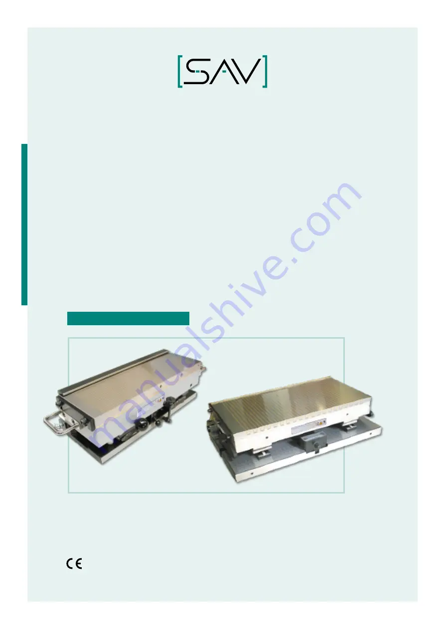
PRÄZISIONS-SINUSTISCH 

MIT ELEKTRO-PERMANENT-

MAGNETSPANNPLATTE / 

ELEKTRO-MAGNETSPANNPLATTE

PRECISION SINE TABLES WITH

ELECTRO PERMANENT MAGNETS / 

ELECTRO MAGNETS

BETRIEBSANLEITUNG . OPERATING INSTRUCTIONS

Version 1.0

just experts

.

SAV  245.09 / .10 / .99

Содержание 245.09

Страница 1: ...H MIT ELEKTRO PERMANENT MAGNETSPANNPLATTE ELEKTRO MAGNETSPANNPLATTE PRECISION SINE TABLES WITH ELECTRO PERMANENT MAGNETS ELECTRO MAGNETS BETRIEBSANLEITUNG OPERATING INSTRUCTIONS Version 1 0 just exper...

Страница 2: ...Originalbetriebsanleitung Aufbewahren zum Nachschlagen Translation of the original operating instructions retain for reference...

Страница 3: ...Personalqualifikation 12 2 3 Pers nliche Schutzausr stung 12 3 Technische Daten 13 3 1 Haftkr fte 14 3 1 1 Nennhaftkraft Verschiebekraft und Polteilung 14 3 1 2 Einfl sse auf die magnetische Haftkraft...

Страница 4: ...piel mit der bergeord neten Maschine gegeben Der Ersteller und Betreiber der Gesamtmaschine soll hiermit in die Lage versetzt werden m gliche Risiken im Betrieb der Gesamtmaschine zu erkennen die sich...

Страница 5: ...die folgenden Pikto gramme Des Weiteren wird mit einem Signalwort Panel eine Gef hrdungsstufe zugeordnet Warnsymbole Allgemeines Warnzeichen Warnung vor elektrischer Spannung Warnung vor magnetischem...

Страница 6: ...re K rperverletzung zur Folge haben WARNUNG WARNUNG Dieser Hinweis kennzeichnet eine Gefahr mit mittlerem Risiko Werden die Sicherheitsbestimmungen nicht beachtet kann die Gefahr m glicher weise Tod o...

Страница 7: ...es Herstellers Die AGBs stehen auf unserer Homepage zum Download zur Verf gung Der Hersteller schlie t Gew hrleistung und Haftungsanspr che bei Personen und Sachsch den aus wenn sie auf eine oder mehr...

Страница 8: ...it Elektro Permanent Magnetspannplatte Elektro Magnetspannplatte 1 Pr zisions Anschlagleiste l ngs 1 Anschlagleiste quer Hebelaschen f r gr ere Ger te Betriebsanleitung Pr zisions Sinustisch Steht auf...

Страница 9: ...tions bereich des Magnetfeldes Mindestabstand 2 m ber den Einsatz von Personen mit Herzschrittmachern aktiven Implanta ten oder ferromagnetischen Fremdk rpern an Maschinen mit Spannmag neten muss indi...

Страница 10: ...n mit hohen Auf und Entmagnetisier Spannungen Ein elektrischer Schlag kann zum Tod oder zu schweren Verletzungen f hren Anschlussdose und Gummikabel unbedingt vor Besch digung sch tzen Um St rungen un...

Страница 11: ...Spannpratzen an den Stirnseiten oder am Basismagnet der Maschine Die Pr zisions Sinustische mit Elektro Permanent Magnetspannplatten Elektro Magnetspannplatten sind ausschlie lich mit der dazu passend...

Страница 12: ...r festgelegt und eingehalten werden Der Betreiber muss dem Bediener die Betriebsanleitung zug nglich machen und sich vergewissern dass der Bediener sie gelesen und verstanden hat Hierzu auch Betriebsa...

Страница 13: ...40x40 mm bei P 4 mm 25x25 mm bei P 13 mm 32x32 mm bei P 18 mm 45x45 mm bei P 25 mm Abnutzbarkeit der Polplatte 8 mm 8 mm Nennhaftkraft 100 N cm bei P 4 mm 90 N cm bei P 13 mm 110 N cm bei P 18 mm 115...

Страница 14: ...zu auch Katalogunterlagen Internet Seiten bzw Anlage beachten Die angegebene Nennhaftkraft pro Werkst ckfl che bezieht sich auf ein Pr fwerkst ck mit 100 x 100 x 40 mm aus St 37 mit geschliffener Ober...

Страница 15: ...den Spannmagnete mit verschiedenen Polteilungen und Polabst nden gefertigt Die Spannfl che wird also abwechselnd mit Nord und S dpolen ausgelegt Der Polspalt besteht aus unmagnetischem Material wie Me...

Страница 16: ...derung der Haftkraft auftritt Durch gr ere Polabst nde erzielt man f r dickere und rohe Werkst cke eine gr ere Tiefenwirkung des Magnet feldes und somit f r derartige Teile eine gr ere Haftkraft Die m...

Страница 17: ...kr fte Ra arithmetischer Mittenrauwert Haftkraft und Luftspalte Luftspalte lassen sich an Werkst cken nicht immer vermeiden Sie entstehen z B durch Materialverformung bei der Vorfertigung Lunker und U...

Страница 18: ...agnete PERM SAV 243 70 42 Querpolteilung 13 18 25 mm P 25 P 18 P 13 Luftspalt in mm Haftkraft in N cm2 50 100 150 0 0 1 0 2 0 3 0 4 0 5 0 6 0 7 0 8 0 SAV 243 71 72 73 SAV 243 40 41 Feinpolteilung 4 mm...

Страница 19: ...en 0 10 20 30 40 50 60 70 80 90 100 Haftkraft in unmagnetisierter Legierungsanteil in 0 20 40 60 80 100 0 10 20 30 Abb 7 Einfluss des unmagnetisierten Legierungsanteils auf die Haftkr fte Bezeichnung...

Страница 20: ...3 50 weich 81 C60 1 0601 3 57 weich 81 Ck60 1 1221 3 65 weich 80 43CrMo4 1 3563 3 62 weich 80 36CrNiMo4 1 6511 4 37 weich 77 C22 1 0402 2 96 verg tet 49 C45 1 0503 3 20 verg tet 48 Ck45 1 1191 3 50 ve...

Страница 21: ...Version 1 0 21 SAV 245 09 10 99 DE 3 TECHNISCHE DATEN 3 2 Typenschild Weitere Daten siehe Typenschilder auf dem Pr zisions Sinustisch Abb 9 Typenschild 1 Magnet Abb 10 Typenschild 2 Sinustisch...

Страница 22: ...nustische ohne Verstellmechanik besteht die Gefahr des Herunterfallens der Oberplatte mit Verletzungs und Quetschgefahr f r die H nde F r Sinustische mit Verstellmechanik besteht Klemmgefahr durch die...

Страница 23: ...durch die Verstellbewegung Bei kleineren Ger ten immer Oberplatte beim Verstellen sicher festhalten Bei Sinustischen mit Verstellmechanik auf Klemmgefahr durch die Verstell bewegung achten Beim Verst...

Страница 24: ...ehmen Beim Anschluss des elektronischen Umpol Steuerger ts bitte separate Be triebsanleitung beachten Um m glichst hohe Genauigkeiten zu erreichen empfiehlt es sich bei der Montage die Polplatte auf d...

Страница 25: ...m Expositionsbereich des Magnetfeldes g ltigen Grenzwerte nach BGV B11 Anlage 2 werden nicht berschritten Spitzenwerte f r Kopf oder Rumpf 2 000 T Mittelwert f r 8h Ganzk rperexposition 0 212 T Spitze...

Страница 26: ...hafte Bedienung k nnen Gegenst nde weggeschleudert werden und schwerste Verletzungen bis hin zum Tod verursachen Der Pr zisions Sinustisch muss sicher auf der Arbeitsplatte der Werkzeug maschine befes...

Страница 27: ...mit Verstellmechanik auf Klemmgefahr durch die Verstell bewegung achten Beim Verstellen besondere Vorsicht walten lassen Betriebsbedingungen Niemals einen schlecht funktionierenden oder besch digten S...

Страница 28: ...fest angezogen sein Messrollen nicht auf Endma auflage fallen lassen Gr ere Sinustische sind mit einem Verstellgetriebe ausger stet Dieses wird ber eine Ratsche betrieben Auf Quetschgefahr f r Finger...

Страница 29: ...kel f r doppelt schwenkbare Sinustische Winkel der einzustellen ist um am Werkst ck zu erhalten arctan tan cos erster Winkel am Werkst ck zweiter Winkel am Werkst ck ben tigter Sinus Einstellwinkel Im...

Страница 30: ...r Entmagnetisierzyklus ber den daf r vorgesehenen Taster einzuleiten 6 3 L sen Bei vertikalem Einsatz des Magneten Werkst ck gegen Herunterfallen sichern Falls der Magnet einen Steckverbinder besitzt...

Страница 31: ...r Umst rzen sichern Zum Heben der Pr zisions Sinustische nur geeignetes und zugelassenes Hebezeug und Schlingen verwenden die gem dem Gewicht der Pr zisions Sinustische ausgelegt sind St rungsbeseitig...

Страница 32: ...t Kabel Anschlussdose und evtl Stecker visuell pr fen In regelm igem Zyklus Polplatte je nach Verschlei fein nachschlichten Dabei die maximale Abarbeitbarkeit der Polplatte nach Kapitel 3 Technische D...

Страница 33: ...rzen sichern Zum Heben der Pr zisions Sinustische nur geeignetes und zugelassenes Hebezeug und Schlingen verwenden die gem dem Gewicht der Pr zisions Sinustische ausgelegt sind St rungsbeseitigung nu...

Страница 34: ...annplatte zur Reparatur an SAV GmbH schicken Steuerger t nicht an Stromversorgung angeschlossen oder defekt Steuerger t pr fen Werkst ck haftet nicht an Magnetspannplatte des Pr zisions Sinustisches H...

Страница 35: ...mechanik besteht die Gefahr des Herunterfallens der Oberplatte mit Verletzungs und Quetschgefahr f r die H nde F r Sinustische mit Verstellmechanik besteht Klemmgefahr durch die Verstellbewegung Bei k...

Страница 36: ...sf hrung als auswechselbare Ausr stung zum Einbau in eine Maschine bestimmt Die Inbetriebnahme ist so lange nicht m glich bis festgestellt wurde dass die Maschine in welche das Ger t ein gebaut werden...

Страница 37: ...qualification 46 2 3 Personal protective equipment 46 3 Technical data 47 3 1 Holding forces 48 3 1 1 Rated holding force displacement force and pole pitch 48 3 1 2 Influences on the magnetic holding...

Страница 38: ...n with the higher level machine The objective is to enable the person company assembling and operating the overall machine to identify possible risks from operation of the overall machine which arise...

Страница 39: ...tables The following symbols apply to the different warnings prohibitions and instructions In addition a second symbol is used to assign a hazard level Warning symbols General warning symbol Warning...

Страница 40: ...h the safety instructions can result in death or serious injuries WARNING WARNING This key word identifies a hazard with a medium risk level Failure to comply with the safety instructions may result i...

Страница 41: ...y The T Cs are available for download from our homepage The manufacturer excludes warranty and liability claims for injury and damage which are caused by one or several of the following Use of the pre...

Страница 42: ...tro permanent magnetic chuck electromagnetic chuck 1 precision stop bar lengthwise 1 stop bar crosswise Lifting lugs for larger devices Operating instructions for the precision sine table available fo...

Страница 43: ...in each individual case and upon consultation with a physician Measurements may have to be carried out In any case the hazard zone has to be limited in such a way that the basic limit of 0 5 mT is not...

Страница 44: ...protect the junction box and rubberised cable against damage To exclude malfunctions and hazards for the operator it must be ensured that the junction box is sealed in particular during wet work and...

Страница 45: ...ide or on the base magnet of the machine The precision sine tables with electro permanent magnetic chuck electromagnetic chuck may only be operated with the appropriate control unit Also observe the p...

Страница 46: ...rly specified and observed The owner must make the operating instructions accessible to the operator and must ensure that the operator has read and understood these Also note the operating instruction...

Страница 47: ...or P 25 mm 40 x 40 mm for P 4 mm 25 x 25 mm for P 13 mm 32 x 32 mm for P 18 mm 45 x 45 mm for P 25 mm Wear layer of the pole plate 8 mm 8 mm Rated holding force 100 N cm for P 4 mm 90 N cm for P 13 mm...

Страница 48: ...note the catalogue documents web pages and the Appendix The stated holding force per workpiece area refers to a test workpiece with 100 x 100 x 40 mm made of steel 1 0037 with polished surface If the...

Страница 49: ...nufactured with different pole pitches and pole spacing The chucking area is consequently designed with alternating north and south poles The pole gap consists of a non magnetic material such as brass...

Страница 50: ...icker and blank workpieces larger pole spacings can achieve greater penetration of the magnetic field and therefore a greater holding force for these parts The minimum workpiece thicknesses must be ob...

Страница 51: ...ece surface on the achievable holding forces Ra calculated mean roughness value Holding force and air gap Air gaps cannot always be avoided on workpieces They can be created for example during upstrea...

Страница 52: ...ng magnets PERM SAV 243 70 42 transverse pole pitch 13 18 25 mm P 25 P 18 P 13 air gap in mm holding force in N cm2 50 100 150 0 0 1 0 2 0 3 0 4 0 5 0 6 0 7 0 8 0 SAV 243 71 72 73 SAV 243 40 41 fine p...

Страница 53: ...0 0 10 20 30 Fig 7 Influence of the unmagnetised alloy component on the holding forces Fig 8 Influence of the heat treatment condition on the holding forces example Short designation as per DIN Materi...

Страница 54: ...CrNiMo4 1 6511 4 37 soft 77 C22 1 0402 2 96 annealed 49 C45 1 0503 3 20 annealed 48 Ck45 1 1191 3 50 annealed 47 C60 1 0601 3 57 annealed 47 Ck60 1 1221 3 65 annealed 47 43CrMo4 1 3563 3 62 annealed 4...

Страница 55: ...Version 1 0 55 EN SAV 245 09 10 99 3 TECHNICAL SPECIFICATIONS 3 2 Type plate For more data refer to the type plate on the precision sine table Fig 9 Type plate 1 magnet Fig 10 Type plate 2 sine table...

Страница 56: ...rushing Sine tables without adjustment mechanism pose a risk of the top plate falling down and causing crush injuries to hands Sine tables with adjustment mechanism poses a risk of jamming during the...

Страница 57: ...ment motion On smaller devices always hold on to the top plate securely during adjustment On sine tables with adjustment mechanism note the risk of jamming during the adjustment motion Proceed with pa...

Страница 58: ...lease note the separate operating instructions when connecting the electronic polarity reversal control unit To achieve the highest possible accuracy we recommend grinding the pole plate on the machin...

Страница 59: ...sure zone of the magnetic field as per BGV B11 Regulation issued by the German Social Accident Insurance Institutions Annex 2 are not exceeded Peak values for head or torso 2 000 T Mean value for 8 h...

Страница 60: ...ard from ejected objects Incorrect operation can cause objects to be ejected causing serious injuries and even death The precision sine table must always be securely attached to the work surface of th...

Страница 61: ...tment On sine tables with adjustment mechanism note the risk of jamming during the adjustment motion Proceed with particular caution during the adjustment Operating conditions Never use a poorly funct...

Страница 62: ...ned Do not let the measuring rollers drop onto the gauge block support Larger sine tables are equipped with an adjustment gear unit This is operated with a ratchet Be aware of the risk of crushing you...

Страница 63: ...13 Swivel angle for double swivel sine tables Angle that has to be set to obtain on the workpiece arctan tan cos First angle on the workpiece Second angle on the workpiece Required sine adjustment an...

Страница 64: ...defined force reduction the de magnetising cycle has to be initiated with the corresponding button between the individual steps 6 3 Releasing When using the magnet vertically secure the workpiece agai...

Страница 65: ...tipping over When lifting the precision sine tables only use suitable and approved lifting gear and slings which are designed for the weight of the precision sine tables Have troubleshooting carried...

Страница 66: ...the electrical connection with cable junction box and any connectors At regular intervals Finely dress the pole plate depending on wear Observe the maximum machining thickness of the pole plate as per...

Страница 67: ...ipping over When lifting the precision sine tables only use suitable and approved lifting gear and slings which are designed for the weight of the precision sine tables Have troubleshooting carried ou...

Страница 68: ...magnetic chuck to SAV GmbH for repair Control unit not connected to the power supply or defective Check the control unit Workpiece not adhering to the magnetic chuck of the precision sine table Holdin...

Страница 69: ...hanism pose a risk of the top plate falling down and causing crush injuries to hands Sine tables with adjustment mechanism poses a risk of jamming during the adjustment motion On smaller devices alway...

Страница 70: ...e equipment Commissioning is not possible until is has been established that the machine into which the device is to be installed complies with the provisions of the EC Directives listed above The fol...

Страница 71: ......

Страница 72: ...rg Nuremberg Deutschland Germany Tel 49 911 9483 0 Fax 49 911 4801426 Mail info sav de www sav de MAGNETSYSTEME MAGNET SYSTEMS UMLAUFENDE SPANNTECHNIK ROTARY WORKHOLDING STATION RE SPANNTECHNIK STATIO...

Отзывы: