background image

Version 1.0 


11 

5


  RADIO COMMUNICATION RANGE 

 
UHF radio signal propagates primarily line of sight, and only slightly bends behind the visible 
horizon due to inhomogeneous atmosphere. Therefore any obstacle, like a hill, a building etc. 
blocking the signal path, may cause significant loss to the signal strength and limit very much 
the radio communication range. 
In case the line of sight connection is blocked, UHF radio signal may reach the receiving 
antenna through reflections from mountain walls, buildings or other infrastructure. Sometimes 
the signal is refracted from sharp edges and find its way behind the obstacles, too. However, 
reflection and diffraction conditions tend to vary in the course of time causing large variation on 
the signal strength and thus risk of loosing temporarily the radio connection. 
In order to maximize the radio range, it is recommended to pay attention to the following items 
in the order of significance. 

1. Antenna height 

Whether the line of sight conditions can be obtained by raising the antennas, the radio range 

will be significantly extended. 

2. Antenna gain and radiation pattern 

Whenever possible, directional antennas should be used to concentrate the signal coverage to 

the area where the receiver operates. It should be also noted that any metal structures very near 
to the antenna violate the radiation pattern of the antenna. 

3. RF cable type 

Low loss RF cable should be chosen for longer feeder lengths from the radio to the antenna to 
avoid extra signal loss. In addition, connectors have to be properly installed, as well as any 
damage to the cable structure must be avoided. 

4. RF interference 

Alien radio transmitters may interfere the signal reception. In that case, the distance of the 

receiver antenna to the interfering transmitter must be increased or an RF filter added to the 
receiver input.  

5. Radio transmitter power and receiver sensitivity 

TX power and RX sensitivity together set the magnitude of the entire link budget. 

As a conclusion, terrestrial UHF radio communication range is heavily affected by local 
topographic, vegetation and infrastructural conditions, and therefore only general guidelines 
can be given to estimate the range simply based on the system hardware (radios, antennas, 
cables etc.). 

Содержание SATELLINE-3AS SLR5

Страница 1: ...Version 1 0 1 SATELLINE 3AS SLR5 Radio Modem Transceiver Short Guide ...

Страница 2: ...ty and applicability to a certain application Under no circumstances is the manufacturer or the developer of a program responsible for any possible damages caused by the use of a program The names of the programs as well as all copyrights relating to the programs are the sole property of SATEL Any transfer licensing to a third party leasing renting transportation copying editing translating modify...

Страница 3: ...to be used in the following countries either on licence free channels or on channels where the operation requires a licence More detailed information is available at the local frequency management authority Countries AT BE BG HR CY CZ DK EE FI FR DE GR HU IS IE IT LV LT LU MT NL NO PL PT RO RU SK SI ES SE CH GB and US WARNING Users of SATELLINE 3AS SLRx radio modem modules in North America should ...

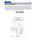
Страница 4: ...ic compatibility and electrical safety and other relevant provisions of Directive 1999 5 EC Therefore the equipment is labelled with the CE marking see below The notification sign informs user that the operating frequency range of the device is not harmonised throughout the market area and the local spectrum authority should be contacted before the usage of the radio modem ...

Страница 5: ...ated at frequencies allocated by local authorities and without exceeding the given maximum allowed output power ratings SATEL and its distributors are not responsible if any products manufactured by it are used in unlawful ways o The devices mentioned in this manual are to be used only according to the instructions described in this manual Faultless and safe operation of the devices can be guarant...

Страница 6: ...TY AND SAFETY INSTRUCTIONS 5 TABLE OF CONTENTS 6 INTRODUCTION 7 1 D DESCRIPTION OF THE PRODUCTS 7 2 T TECHNICAL SPECIFICATIONS 8 2 1 S SATELLINE 3AS SLR Technical specifications 8 2 1 1 Power supply 8 3 U USER INTERFACE 9 3 1 L LED indicators 9 4 S SERIAL INTERFACE 10 5 R RADIO COMMUNICATION RANGE 11 ...

Страница 7: ...include both public organisations and private individuals SATEL is the leading European manufacturer of radio modems SATEL radio modems have been certified in most European countries and also in many non European countries 1 DESCRIPTION OF THE PRODUCTS SATELLINE 3AS SLR5 is member of the versatile SATELLINE 3AS radio modem family SATELLINE 3AS SLR5 is a UHF radio transceiver modem It provides a tr...

Страница 8: ...r power 0 1 0 2 0 5 and 1W 2 1 1 Power supply The allowed operating voltage is 6 VDC 5 The radio modem must only be connected to a power supply with an adequate current output NOTE There is a galvanic connection between signal ground SGND pin 10 ground GND pin 13 outer conductor of antenna connector and modem casing The power cable Vb and GND must be connected to a power supply with a proper outpu...

Страница 9: ... RSSI Signal strength No data Data detected and ok Data detected but weak signal RX TX Data indicator No data transferred Data transfer Mode Communication or programming Data Mode Programming mode Description of the LED indicators o Power indicates the status of Power ON OFF o Signal strength indicates the strength of the received signal o RX TX indicates that the radio modem is receiving or trans...

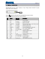
Страница 10: ... RD TTL Output Receive Data DTE 4 GPO DCD TTL Output General purpose output Carrier Detect output 5 RTS TTL Input Request to Send by DTE 6 CTS TTL Output Clear to Send by modem 7 CPI CFG TTL Input General Purpose Input Config mode 8 PWR 6 0V Input 6V 5 DC Voltage Supply 9 GPIO TTL input output General Purpose IO 10 GND GND Signal and Chassis Ground 11 NC Not Connected 12 NC Not Connected 13 GND GN...

Страница 11: ...ennas the radio range will be significantly extended 2 Antenna gain and radiation pattern Whenever possible directional antennas should be used to concentrate the signal coverage to the area where the receiver operates It should be also noted that any metal structures very near to the antenna violate the radiation pattern of the antenna 3 RF cable type Low loss RF cable should be chosen for longer...

Отзывы: