background image

SATEL CA-64 

SM 

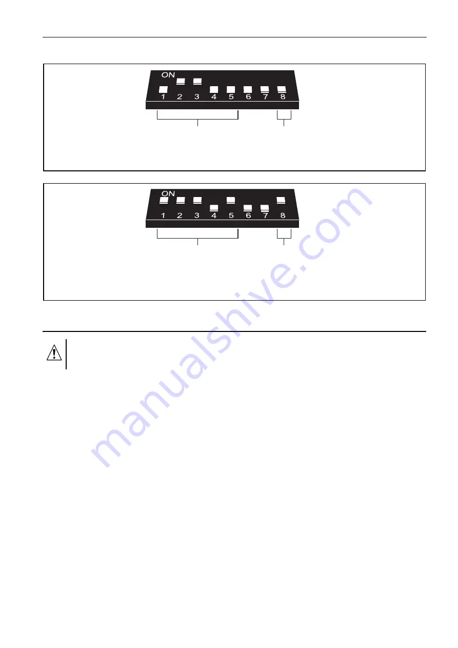
The DIP-switches 6 and 7 are not used. 


Fig. 2. Example of setting the DIP-switches. 


Fig. 3. Example of setting the DIP-switches (address required when interfacing with the 

VERSA control panels). 


2.  Installation and start-up 

All connections should only be made when power supply of the alarm system is 
disconnected. 

1.  Secure the expander in the control panel housing. 
2.  Connect the CLK and DTA cables to the corresponding communication bus of control 

panel. 

3.  Connect the PIN5 plug to the corresponding socket on the electronics board of control 

panel. 

4.  Using the DIP-switches, set the expander address. 
5.  Turn on power supply of the alarm system. 
6. Start the identification function in the control panel. 

2.1 Recording the voice messages 

1.  Set the DIP-switch 8 into the ON position. 
2. Press the MSG. NO button to select the number of message to be recorded. The 

message number is displayed by means of LEDs as shown in Table 1. 

3.  Press the REC button (the REC LED will go on) and dictate the message content into the 

microphone. The module is provided with an automatic system for recording level control. 
The recording will automatically end after 15 seconds (the REC LED will go out). 

Note:

  It is recommended that the switch 8 be set into OFF position when recording is over. 

address: 

message recording: 

disabled 

address: 

23 

message recording: 

enabled 

Содержание CA-64 SM

Страница 1: ...set of DIP switches for setting individual address of the module and for disabling enabling the message recording see section DIP SWITCHES 2 SYSTEM LED indicating communication with the control panel LED is blinking data exchange with the control panel LED is lit no communication with the control panel 3 LEDs to provide information on voice messages M3 M2 M1 M0 present the number of recorded playe...

Страница 2: ...LED ON 2 3 4 5 6 7 8 9 10 11 12 13 14 15 Table 1 The way of message number presentation 1 1 DIP switches The DIP switches from 1 to 5 are to be used for address setting The address must be different from that of the other modules connected to the communication bus of alarm control panel In order to determine the expander address add up the values set on individual switches as shown in Table 2 DIP ...

Страница 3: ...IP switches set the expander address 5 Turn on power supply of the alarm system 6 Start the identification function in the control panel 2 1 Recording the voice messages 1 Set the DIP switch 8 into the ON position 2 Press the MSG NO button to select the number of message to be recorded The message number is displayed by means of LEDs as shown in Table 1 3 Press the REC button the REC LED will go o...

Страница 4: ...he PLAY button the PLAY LED will go on The message will be played back 3 Technical data Number of stored voice messages 16 Maximum message duration 15 s Supply voltage 12 V DC 15 Maximum current consumption 65 mA Dimensions of electronics board 57x80 mm Weight 41 g The latest EC declaration of conformity and product approval certificates are available for downloading on website www satel pl SATEL ...

Отзывы: