40
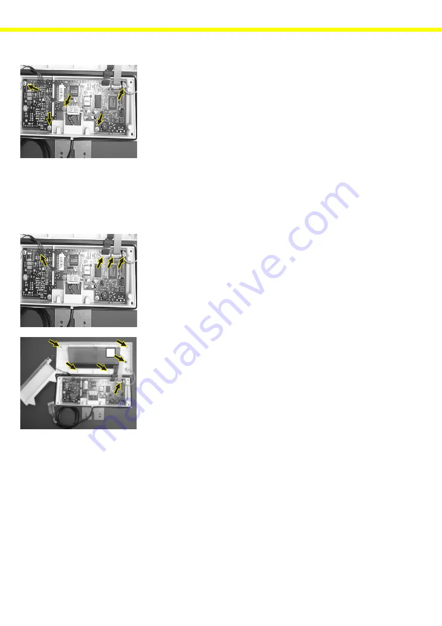
– Fix the new PCB in place with the 5 fastening screws.
– Reconnect all the connecting cables and plugs.
– Position the seals.
– Position the front panel and fasten it with the 4 screws.
– Connect the balance to AC power and turn it on.
– The error code “
Err340
” is displayed.
– Turn the balance off and back on again.
– If the operating menu EEPROM was not moved from the old to the new
PCB, the user’s settings will need to be input now (via the INPUT mode
and the MENU).
Replacing the Display and Control Unit, Backlighting Module, Keypad Overlay
– Disconnect the balance from AC power.
– Open the display and control unit (see page 28 for instructions).
– Disconnect the wires to the keypad overlay, the display, the ground con-
nection and the display backlighting.
– The front panel is now accessible
– Remove the 5 tin screws and remove the backlighting module.
– You can now remove and replace the display unit.
– Remove the adhesive keypad overlay from the front panel, remove any
traces of adhesive remaining on the panel, and affix the new keypad over-
lay.
– Re-connect the ground connection to screw (B), position the display and
the backlighting module, and fasten them with the 4 tin screws.
– Reconnect all the connecting cables and plugs.
– You can now close the display and control unit (see page 27).
Replacing the Balance PCB
Note:
To replace the balance PCB, you need the SARTOCAS Service Program for
PCs, version 1.10 or newer, or the PSION server, CAS version 4.5 or newer.
Before replacing the PCB, you should attempt to copy the data from the old
PCB and store it.
This is done using the SARTOCAS Service Program for PCs, version 1.10 or
newer, or the PSION server, CAS version 4.5 or newer.
The required procedures are described in the corresponding program instruc-
tions.
If it is not possible to read the data records or if no replacement PCB is avail-
able, you can order a pre-programmed PCB from the Sartorius factory. Make
sure you include the correct balance model and serial number when ordering
the PCB.
Anzkop1a.TIF
Anzkop1a.TIF
Anzkop-1.TIF
B
Содержание Master Pro LA12000P
Страница 50: ...50 Spare part list LP LA LP LA Exploded View Diagram 1 LP_exp_1 WMF LA LP...
Страница 52: ...52 LP LA Exploded View Diagram 2 LP_exp_2 EPS...
Страница 54: ...54 LP LA Exploded View Diagram 3 LP_exp_3 EPS...
Страница 56: ...56 LP_exp_4 EPS LP LA Exploded View Diagram 4...
Страница 58: ...58 LP_exp1a WMF LP LA Exploded View Diagram 1a LP LA...
Страница 60: ...60 LP LA Exploded View Diagram 2a LP_exp2a WMF A 201 202 211 203 207 206 216 215 214 B 217 208 218...
Страница 62: ...62 LP_exp_3a WMF LP LA Exploded View Diagram 3a 301 302 308 309 305 306 307 304 305...


