13
6.
6.
6.
6.
Quality Control
Quality Control
Quality Control
Quality Control
6.1
6.1
6.1
6.1
Inspecting weld quality
Inspecting weld quality
Inspecting weld quality
Inspecting weld quality
The BioWelder® is designed to make reproducible and reliable connections,
however it is still critical to inspect the weld prior to use.
Important:
Important:
Important:
Important:
Allow the weld to cool down for 2-3 minutes before inspection to achieve optimal
strength.
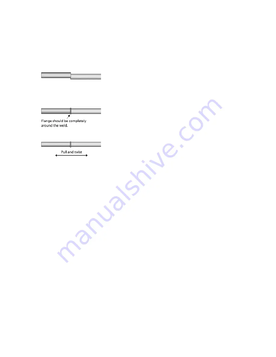
1. Axial alignment
Check that the tubing is axially aligned. If the tubing is offset, the weld will
be weaker on one side. Do not use such welds. Contact your Service
Representative to realign the unit.
2. Uniform weld
Check that you see a flange all around the weld. This indicates that the weld is
uniform in the radial direction. If you do not see a flange around the weld, discard
the weld. Make sure that you are using the correct tubing. If you are unable to get
a uniform flange contact your Service Representative for help.
3. Good tensile strength
Pull GENTLY at the weld. It should not come apart or start to crack
6.2
6.2
6.2
6.2
Using different
Using different
Using different
Using different types of hoses
types of hoses
types of hoses
types of hoses
It is possible to weld thermoplastic tubings like C-Flex®, Raumedic® FluiSoft
TM
,
Pharmed® and Sanipure®.
It is not possible to weld non-thermoplastic formulations such as PTFE, silicone,
or natural rubber. A list of compatible tubing is provided in the Appendix 2.
Different tube formulations have varying melt points. Most tubes can be joined
satisfactorily using the default settings.
Your machine is set to the tubes types
Your machine is set to the tubes types
Your machine is set to the tubes types
Your machine is set to the tubes types
you selected on your order.
you selected on your order.
you selected on your order.
you selected on your order.
6.3
6.3
6.3
6.3
Welding different parameters
Welding different parameters
Welding different parameters
Welding different parameters
The BioWelder® is capable of joining tubes of various outer diameters. A set of
tubes holders specific to each tubing outer diameter must be purchased. These
holders are available for a minimum tubing outer diameter (OD) of 1/4 inch to a
maximum tubing OD of 3/4 inch.
Each holder set consists out of two blue (left) and two red (right) tube holders.
All four holders must be changed as a set. Holders can simply be snapped in and
out. The machine reads the coded holders and runs the appropriate stored
program.


