Connections
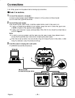
Turn off the power for all equipment before making any connections.
Basic Connections
1
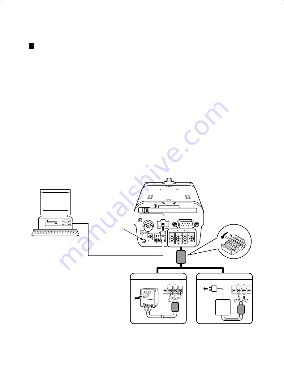
Connect the camera to a computer.
Connect a cable between the ETHERNET connectors of the camera and the computer.
Use a crossed wire-type Ethernet cable.
2
Connect the power supply.
After connecting the power supply, install the supplied ferrite core A to the power cord.
•
If using a commercially-available 24 V AC adapter, always be sure to connect the ground wire
(18AWG or higher) to the ground terminal. (Figure 1)
•
If using a 12 V DC power supply (sold separately: DSA-0151CD-12J), make the connections as
shown in Figure 2.
Note:
•
In order to avoid any problems with the camera and the power supply, take sufficient care to
ensure that the polarities are correct when connecting the power supply.
•
When the accessory ferrite cores are attached, they will increase the load on the cable, so after
doing the installation, adjust the cable accordingly.
3
Insert the power cord plug into a wall outlet.
The POWER indicator B will illuminate.
PC CARD
RS-232C
ALARM IN
OUT
MODEM
PC
COM
AC24V
DC12V
GND
1 2
ETHERNET
POWER
MONITOR
OUT
24 V AC connection
Figure 1
Figure 2
12 V DC connection
B
Computer
Ethernet cable
(crossed wire-type cable)
AC24V
DC12V
GND
AC24V
DC12V
GND
A
CLASS 2 WIRING
1
3
2
2
L5AM2/XE (VCC-WB4000P) GB 2003, 6, 6
English
– 9 –


