background image

CAMERA Settings

Using an IR lamp to illuminate
during black & white monitoring
in COLOR mode

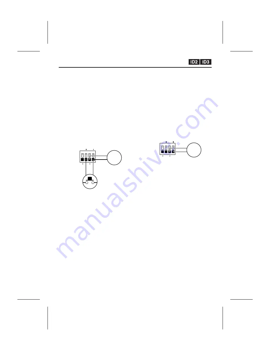
When using COLOR mode, connect a device
such as an IR lamp to the ALARM OUT terminal
and connect an infrared sensor (for forcibly
switching to black & white monitoring) to the D/N
IN terminal. (Figure 1)
The IR lamp can then be made to illuminate
when monitoring switches to black & white.

Note: Change the ALARM OUT setting for

COLOR mode to “NO” or “NC”. However,
in such cases, the ALARM OUT output
and alarm output settings will be disabled
during alarm recording. (p. 32)

(Connection example: Figure 1)

1

Change the DAY/NIGHT setting to COLOR
mode.
Automatic switching to black & white
monitoring will then be possible using the
infrared sensor that is connected to the D/N
IN terminal.

2

At the same time as the camera images
switch to black & white, an ALARM OUT
(NO/NC) signal will be output and the
connected IR lamp will illuminate.
Note: 
The IR lamp will illuminate only while

black & white monitoring is being
carried out. Set the polarity so that a
signal is output during black & white
monitoring.

Using an IR lamp to illuminate
during black & white monitoring
in TIMER mode

When using TIMER mode, connect a device
such as an IR lamp to the ALARM OUT terminal.
(Figure 2)
The IR lamp can then be made to illuminate
during the black & white monitoring period.

Note: Change the ALARM OUT setting for

TIMER mode to “NO” or “NC”. However,
in such cases, the ALARM OUT output
and alarm output settings will be disabled
during alarm recording. (p. 32)

(Connection example: Figure 2)

1

Change the DAY/NIGHT setting to TIMER
mode.
Set the switching time and switch to black &
white monitoring.

2

At the same time as the camera images
switch to black & white, an ALARM OUT
(NO/NC) signal will be output and the
connected IR lamp will illuminate.
Note: 
The IR lamp will illuminate only while

black & white monitoring is being
carried out. Set the polarity so that a
signal is output during black & white
monitoring.

ALARM IN

OUT

COM

D/N IN

IR lamp

Infrared sensor

ALARM IN

OUT

COM

D/N IN

IR lamp

L5AM2/US (VCC-WB4000)  GB  2003, 6, 6

English

– 31 –

Содержание VCC-WB4000

Страница 1: ...UCTION MANUAL Network Camera VCC WB4000 About this manual Before installing and using this unit please read this manual carefully Be sure to keep it handy for later reference L5AM2 US VCC WB4000 GB 2003 6 6 ...

Страница 2: ...and Recording 40 A Using Only Post alarm Recording 40 B Pre alarm Post alarm Recording 40 Recording New Alarm Data 41 Fixed Settings During Pre Post Alarm Recording 41 Saving to an Expansion Memory Card 42 Viewing Live Images 43 Viewing the View Frame Screen 44 Playing Back Alarm Data 45 Playing Back Alarm Data in the Camera s Internal Memory 45 Descriptions of Alarm Operation Buttons 45 Playing B...

Страница 3: ...in accordance with the instructions may cause harmful interference to radio communications However there is no guarantee that interference will not occur in a particular installation If this equipment does cause harmful interference to radio or television reception which can be determined by turning the equipment off and on the user is encouraged to try to correct the interference by one or more o...

Страница 4: ...io speakers the magnetic field they generate will distort the image Protect from humidity and dust To prevent damages to the camera do not install it where there is greasy smoke or steam where the dampness may get too high or where there is a lot of dust Protect from high temperatures Do not install close to stoves or other heat generating devices such as spotlights etc or where it could be subjec...

Страница 5: ...witch that is set to detect abnormalities so that images can be recorded and played back when an alarm occurs Day Night Function The day night function allows the camera to adapt to a variety of different luminance conditions so that color images are monitored during daytime but under conditions of low illumination such as nighttime it switches automatically to black white Accessories 1 Setup CD R...

Страница 6: ...nting bracket sold separately select a location that is strong enough to bear the full weight of the camera and the mounting bracket for long periods and install the camera and mounting bracket securely 3 Flange back locking screws p 8 4 Flange back adjustment dial p 8 5 PC CARD slot Use this slot to insert a memory card or wireless LAN card Note Make sure that the camera s power is turned off bef...

Страница 7: ...n monitoring switches to black white images Output rating 18 V 25 mA D Ground terminal COM F Power supply input terminals AC24V DC12V GND G RS 232C connector Use this connector to connect the camera to a modem for transmission of data along telephone lines or for connecting the camera to a computer Use the PC MODEM select switch to change the camera operation between modem and computer operation H...

Страница 8: ...lange back attach the C mount adapter ring option to the lens before attaching the lens to the camera 3 Connect the lens iris plug to the lens iris output connector of the camera 1 control coil 3 drive coil 2 control coil 4 drive coil Connecting to the lens iris plug Lenses from other manufacturers may have different plug shapes and specifications In such cases you may need to rewire the lens iris...

Страница 9: ...mera and the monitor s video connector VIDEO IN 2 Turn on the camera s power Adjust the flange back while viewing the camera images on the monitor 3 Use a Phillips screwdriver to loosen the flange back locking screws 4 Move the zoom lens to the telephoto setting and then use the lens focus ring to adjust the focus 5 Move the zoom lens to the wide angle setting and then use the flange back adjustme...

Страница 10: ... DSA 0151CD 12J make the connections as shown in Figure 2 Note In order to avoid any problems with the camera and the power supply take sufficient care to ensure that the polarities are correct when connecting the power supply When the accessory ferrite cores are attached they will increase the load on the cable so after doing the installation adjust the cable accordingly 3 Insert the power cord p...

Страница 11: ...se a straight type Ethernet cable If connecting to an ADSL modem or to some other type of device refer to the documentation provided with the device for details on what type of connection method should be used PC CARD RS 232C ALARM IN OUT MODEM PC COM AC24V DC12V GND 1 2 ETHERNET POWER MONITOR OUT Ethernet cable straight type Ethernet switching hub LAN CLASS 2 WIRING PC CARD RS 232C ALARM IN OUT M...

Страница 12: ...t the installation 2 Wired LAN Settings p 15 Connect an Ethernet cable between the camera and the computer and then make the required initial settings such as the computer IP address user name password and language When these settings are completed the initial camera screen will be displayed This section gives descriptions of the various parts of the initial screen for you to refer to 3 NETWORK SE...

Страница 13: ...ive of the computer 3 Click Start and then click Run 4 Type D Setup exe Type the drive letter for the CD ROM drive of the computer in place of D 5 Click the OK button After a short wait the installation window will appear Note Simply answer the prompts that appear on the screen in order to continue installing the software The installation program has been set up beforehand to install the software ...

Страница 14: ...software will start and the window display will change to show the installation progress 10 Click the Finish button This completes the installation of the plug in software Uninstalling the plug in software To uninstall the plug in software select Add Remove Programs from the Windows Control Panel and delete J2KCORE L5AM2 US VCC WB4000 GB 2003 6 6 English 13 ...

Страница 15: ...rols and plug ins in the ActiveX controls and plug ins section 2 Click Enable for Active scripting in the Scripting section and then click the OK button Cookie Settings The camera uses cookies If using Internet Explorer Version 6 0 as the web browser select Internet Options from the Tools menu click the Privacy tab move the slide bar to the Medium or lower position and then click the OK button Not...

Страница 16: ...ress is set to 192 168 0 2 so type in a spare number that is 3 or higher for the IP address Example 192 168 0 101 Subnet mask setting Type in 255 255 255 0 3 Start the web browser on the computer type http 192 168 0 2 into the location bar and then press the Enter key The password entry window will be displayed 4 Type in the username ID3 and the password 3333 and then click the OK button The langu...

Страница 17: ...t are being transmitted Available settings AUTO default setting The live images being transmitted are automatically adjusted in accordance with the computer FINE The live images being transmitted are displayed at high quality The actual image display quality will vary depending on the original quality at the time of transmission Note The quality of the images will vary depending on the capabilitie...

Страница 18: ...n speed when the camera is connected directly to the computer LANGUAGE button Click this button if you would like to change the language The language selection screen will be displayed STATUS button Used when checking firmware versions and information relating to the camera 3 Network disconnect button Click this button to shut down operation of the network camera The following message will be disp...

Страница 19: ...OUT TIME is set to REMOTE The output status can be turned on and off repeatedly by clicking the indicator 8 BEEP OFF indicator p 34 If ALARM SOUND MODE is set to USE this display appears at the same time as the buzzer sounds when an alarm is detected Click the indicator to stop the alarm buzzer from sounding The alarm buzzer will stop automatically when alarm recording is complete 9 FRAME RATE set...

Страница 20: ...ON RATIO and RESOLUTION settings to levels that will not interfere with the operation of the network If the amount of data being transferred is too large for the network environment it may have an adverse effect on other network operations The picture quality and image resolution cannot be changed when pre alarm recording has been set H IMAGE MODE setting default setting COLOR Select whether live ...

Страница 21: ...vailable User Operator and Administrator and separate passwords can be set for each level The factory default settings are shown in Table 1 p 23 and the range of operations varies as indicated for each access level Note It is recommended that you change the passwords whenever possible for security purposes p 21 5 NETWORK SPEED This sets the speed of data transmission by the camera Available settin...

Страница 22: ...iority In such cases the Operator level user will be disconnected and the message THE UNIT IS DISCONNECTED will be displayed on their screen If an Operator or Administrator attempts to access the camera while another user with the same access level is accessing the camera the second access will have priority In such cases the first access will be disconnected and the message THE AUTHORIZED USER LO...

Страница 23: ...image screen will be displayed Note If the ID1 password is blank a single image live image screen will always be displayed To return to normal password entry type in a password for ID1 example 1111 Changing the Access Level ID2 or ID3 If live images are monitored without using a password the SET button will change to CHANGE ID To change the access level to ID2 or ID3 follow the procedure below 1 C...

Страница 24: ...e table below Table 1 Username password Access level For Administrator access level All operations and settings can be carried out Username ID3 Password 3333 For Operator access level Only the following buttons can be operated Username ID2 Password 2222 For User access level Only the following buttons can be operated Username ID1 Password 1111 The transmission setting menu in the live image screen...

Страница 25: ... time has not been set when you log in default setting it will be set automatically LOGIN The time is set automatically each time you log in OFF The time is not set Note Make sure that the computer s time is set correctly 4 DAYLIGHT SAVING MODE The daylight saving settings are displayed when USE is selected from the drop down list box Available settings USE Daylight saving time is used When set to...

Страница 26: ...new setting If you click the live image screen the initial camera screen will be displayed 2 CAMERA TITLE This sets the camera title that is displayed in the live image screen The default camera title is NET_CAM 3 IRIS Select automatic iris or electronic iris Available settings AI Automatic iris default setting EI Electronic iris Note The electronic iris does not have an electronic shutter setting...

Страница 27: ...adjustments to the white balance When MANUAL is selected you can adjust the red and blue colors It can be used when the AUTO setting does not give correct color reproduction Setting manual white balance MANUAL Click the and buttons repeatedly to adjust the settings for R red and B blue Setting range 0 to 255 Note The red or blue component becomes stronger when the setting is higher 9 GAMMA Select ...

Страница 28: ...lick the SET button The new camera title will be saved and it will appear in the camera title display of the live image screen DAY NIGHT Settings The images being monitored can be switched between color and black white depending on the luminance of the objects being monitored The DAY NIGHT settings can be selected from one of four modes AUTO COLOR B W and TIMER Click the DETAIL button in the DAY N...

Страница 29: ...terference will also increase 3 ALARM OUT Set when using COLOR and TIMER mode When an IR lamp or similar device is connected to the ALARM OUT terminal at the rear of the camera the IR lamp can be made to illuminate when the mode switches from color to black white Available settings OFF NC NO 4 LEVEL Set when using AUTO mode This sets the luminance for switching automatically between color and blac...

Страница 30: ...an be output from the ALARM OUT terminal when monitoring switches to black white An IR lamp can be connected so that it illuminates at such times 4 Set POLARITY to NO example The D N IN terminal at the rear of the camera can be used to forcibly switch monitoring from color to black white NO Normal open Normally open so that when closed monitoring switches between color and black white NC Normal cl...

Страница 31: ...e DAY NIGHT field and set MODE to TIMER 2 Set AGC Gain to 12 dB example 3 Set ALARM OUT to NO example A signal can be output from the ALARM OUT terminal when monitoring switches to black white An IR lamp can be connected so that it illuminates at such times 4 Set BURST to OFF example 5 Change the TIMER ON setting to 20 00 and the OFF setting to 04 00 6 Click the SET button This completes the TIMER...

Страница 32: ...minate only while black white monitoring is being carried out Set the polarity so that a signal is output during black white monitoring Using an IR lamp to illuminate during black white monitoring in TIMER mode When using TIMER mode connect a device such as an IR lamp to the ALARM OUT terminal Figure 2 The IR lamp can then be made to illuminate during the black white monitoring period Note Change ...

Страница 33: ...nsor or a motion detector the ALARM indicator and the ALARM DATA indicator illuminate simultaneously When images are being recorded in the camera s internal memory the ALARM indicator switches off and the ALARM DATA indicator illuminates red Playback of alarm recording images is possible at this time Alarm checking Output When an alarm has been detected by either an external alarm sensor or a moti...

Страница 34: ...ttings AND An alarm is generated when both the external alarm and the motion sensor receive alarm input OR An alarm is generated when either the external alarm or the motion sensor receives alarm input 6 ALARM OUT This is used to make settings for a device such as a buzzer that is connected to the ALARM OUT terminal at the rear of the camera when an alarm is input When NC normal close or NO normal...

Страница 35: ...larm is detected is recorded into the camera s internal memory The recording capacity of the internal memory is set to a default of approximately 16 MB per alarm event 1 ALARM DATA SIZE This sets the size for alarm data that is recorded into the internal memory The pre post selection ratio for the alarm recording area will vary depending on the size that is set Available settings 16 12 8 4 MB All ...

Страница 36: ...example you can cause a buzzer that is connected to the ALARM OUT terminal to sound For details see 6 ALARM OUT 5 Set ALARM OUT MODE to ALARM OUT 6 Use the drop down list box to change the ALARM OUT TIME setting to 60 sec example 7 Set ALARM SOUND MODE to USE 8 Set RECORD SIZE to CC If CC is selected recording will only be carried out while an alarm is being input If FULL is selected recording wil...

Страница 37: ...ion Detector Level Sensitivity Setting for further details p 38 5 Set the sensor marks These correspond to the live image screen and the sensing area 1 Move the pointer to the same position grid area as the area of the live image screen that you would like sensing to be carried out and then click the mouse button A sensor mark ú will be displayed Click in the same place once more to clear the mark...

Страница 38: ...the higher will be the sensitivity Refer to Motion Detector Level Sensitivity Setting for further details p 38 5 Set the sensor marks Refer to MOTION DETECTOR SET Settings 6 Set ALARM MODE to OR example An alarm will then be triggered if either the motion detector or the external alarm sensor detects something Refer to 5 ALARM MODE for details p 33 7 Click the SET button 8 Set ALARM OUT ALARM OUT ...

Страница 39: ...insert sensor marks in the optimum positions and to set the sensitivity Remote Alarm Operations You can use the REMOTE ALARM indicator to set alarm output to come out from the ALARM OUT terminal at the rear of the camera for a specified period or continuously regardless of the actual alarm detection status A Alarm Output for a Specified Period 1 Set ALARM OUT to NO example 2 Set ALARM OUT MODE to ...

Страница 40: ...ive image screen The REMOTE ALARM indicator gray will be displayed in the initial screen 4 While monitoring the live images click the REMOTE ALARM indicator The REMOTE ALARM indicator will illuminate orange and an alarm will be output continuously If you repeatedly click the indicator the continuous alarm output will turn on and off each time you click the indicator 1 2 3 L5AM2 US VCC WB4000 GB 20...

Страница 41: ...ost alarm Recording When an alarm is detected recording is assigned between the pre and post alarm recording areas in the ratio specified You can increase or decrease the length of time that images are recorded before an alarm is detected 1 Set BUFFERING AREA to PRE POST 2 8 2 If an alarm is detected in the live image screen the indicators will illuminate as follows and the images will be recorded...

Страница 42: ... downloaded as continuous images Fixed Settings During Pre Post Alarm Recording If the pre alarm post alarm recording area ratio is set to something from 1 9 to 5 5 so that pre alarm recording can be carried out the transmission settings PICTURE QUALITY RESOLUTION and IMAGE MODE COLOR are fixed Example 1 If PRIORITY is set to PICTURE QUALITY The image quality during pre and post alarm recording wi...

Страница 43: ...e internal memory will be automatically moved to the memory card The data will be deleted from the recording areas of the internal memory at this time 3 The ALARM DATA indicator green will illuminate If alarms are repeatedly detected in this condition the alarm data will be automatically moved to the memory card Note If there is no free space on the memory card the indicator will illuminate red If...

Страница 44: ... are displayed Settings relating to the transmission of images such as PICTURE QUALITY and RESOLUTION are set using the drop down list boxes in the transmission setting area 2 The transmission speed will increase or decrease depending on the settings that are made here Note If you would like to change the camera settings using the live image screen click the mouse on the live image screen to direc...

Страница 45: ...a screen size of 720x480 regardless of the screen size that has been set in the live image screen To return to the live image screen click the BACK button Note Even if the image size has been set to a smaller size 160x120 or 320x240 the images will still be displayed at a size of 720x480 In this case the image resolution will appear coarser L5AM2 US VCC WB4000 GB 2003 6 6 44 English ...

Страница 46: ...dby You can then click the PLAY button to play back the data 2 PLAY button Click this button during playback standby or when playback is paused to start playback 3 STOP button If you click this button while playback is in progress playback will stop 4 FRAME RATE You can select the playback speed for alarm images using the drop down list box If you change the speed while alarm images are in the pro...

Страница 47: ...is complete the BUFFER DATA VIEW screen will be displayed the PRE or POST indicator will illuminate and playback of the alarm images will start automatically When playback is finished the END indicator will be displayed Playing Back Alarm Images Stored in a Computer Refer to p 50 for details on saving alarm data into a computer 1 Using Windows Explorer click on the download destination and then do...

Страница 48: ...e image number The image number changes depending on the playback status 4 TOP Displays the first image in the data and also displays the first image number 5 PREVIOUS Reverses playback one frame at a time 6 REVERSE Reverses playback 7 STOP If clicked while playback is in progress playback stops 8 PLAY Starts playback 9 NEXT Carries out playback one frame at a time F END Displays the last image in...

Страница 49: ...a to be deleted and then click the DELETE button The alarm data delete confirmation dialog box will be displayed 3 Click the OK button The alarm data will be deleted Note When deleting more than one set of alarm data at the same time the message THE UNIT IS REMOVING ALARM DATA will be displayed briefly and then the selected alarm data will be deleted L5AM2 US VCC WB4000 GB 2003 6 6 48 English ...

Страница 50: ... images will be saved at the selected resolution The extension used for the saved images will be jp2 Saving Alarm Images onto a Computer as Still Images Alarm images can be saved as still images in the computer s storage area in JPEG2000 format 1 Right click the mouse on the alarm image to be saved The images will be paused and an image save pop up menu will be displayed 2 Click Save JPEG2000 File...

Страница 51: ...File Download pop up menu is displayed click Save The Save As dialog box will be displayed 4 Specify the saving destination and the filename and then click the Save button The download will then start Do not close the network camera window 5 Use Windows Explorer to open the saving destination folder 6 Double click the alm_viewer_XXXX html file The download will start When the download is finished ...

Страница 52: ...ert the wireless LAN card into the camera Figure 1 1 Insert a commercially available wireless LAN card into the camera so that it is facing in the right direction and then fold down the knob in the direction of the arrow This will lock the card in place 2 To remove the card push the knob in the direction of the arrow to release the card Note Consult your local dealer for advice on purchasing a wir...

Страница 53: ...AN device The ESS ID can consist of up to 32 alphanumeric characters 4 Set the encipherment method Because the camera and the wireless LAN device communicate by means of radio waves there is the possibility that wireless packets could be intercepted and decoded by outsiders It is recommended that you complete the encipherment setting in order to provide greater security p 53 5 Make the TCP IP sett...

Страница 54: ... key can be set Rules for encryption key entry WEP40 WEP64 The encryption key can consist of up to 5 alphanumeric characters WEP128 The encryption key can consist of up to 13 alphanumeric characters Encipherment Settings If you do not type in the same encryption key that has been set for the wireless LAN device communication will not be possible Make a note of the encryption key and type it in Exa...

Страница 55: ...he power off and then back on again 4 Camera PPP settings Make the settings for transmitting alarm data Refer to DIAL TO PROVIDER Settings p 56 for details Note After making the PPP settings close the camera setting screen 5 Install the Network Archiving Software onto the computer Note After installing the software close the software window 6 Make the Camset settings Camset only makes the settings...

Страница 56: ...ned by the ISP in this case FTP PORT NUMBER Type in 21 FTP PASSIVE Set to NO USE CAMERA ID Type in a unique 4 character camera name 5 Click the SET TO CAMERA button The settings will be loaded into the camera 6 Click the SAVE INFO FILE button The settings will be applied to the Network Archiving Software 7 Close the Camset window Note The camera cannot be accessed using the computer s web browser ...

Страница 57: ...PAP Only PAP authentication is used CHAP Only CHAP authentication is used 5 IP address and error display 1 AUTO IP ADDRESS The IP address is only displayed while the camera is connected 2 ERROR INFO Shows the most recent error information during a PPP connection Display details Modem timeout or Not connected Line connection error Line disconnected PPP connection error PPP authentication error PPP ...

Страница 58: ... control In may cases the modems may be set up to use hardware RTS CTS flow control In such cases you will need to use AT command settings to change the modem settings to software flow control Modem commands consist of a single line starting with the letters AT followed by the commands as shown below Generally you should issue an AT K4 command to switch to software flow control but this may vary d...

Страница 59: ... PPP connection 4 Select the authentication settings AUTHENTICATION This sets the authentication protocol to be used when connecting to the access point It should normally be set to AUTO Available settings AUTO default setting PAP or CHAP is chosen automatically as required PAP Only PAP authentication is used CHAP Only CHAP authentication is used 5 Click the SET button The PPP SET screen will be d...

Страница 60: ...n click the SET button The setting will then be saved The default setting for the communication speed is 19200 bps Note If you click the LIVE VIEW button the display will return to the live image screen LANGUAGE Selection Click the LANGUAGE button to change the language The language selection screen will then be displayed Once a language is selected the language setting is stored in memory so the ...

Страница 61: ...the LIVE VIEW button the display will return to the live image screen 1 FIRMWARE VERSION This shows the version number for the camera s firmware 2 SUB MICROCOMPUTER VERSION This shows the version number for the camera s sub microcomputer 3 PCMCIA SOCKET STATUS This shows the usage status for the PC card slot 1 2 3 L5AM2 US VCC WB4000 GB 2003 6 6 60 English ...

Страница 62: ...puter being used FTP File Transfer Protocol A protocol communication standard for transmitting files via the Internet This communication protocol allows files and data to be transferred via the Web whereas previously it was only possible using e mail Hard disk A storage device for large quantities of data that is used by equipment such as computers It contains a flat disc that is coated with magne...

Страница 63: ...network devices and determines what route should be used for the information to be transmitted to and from these devices SMTP Simple Mail Transfer Protocol A protocol communication standard for sending and receiving electronic mail via the Internet and Intranets It controls the flow of mail between servers and is also used when clients send mail Stop bit A symbol that is added at the end of a byte...

Страница 64: ...the ratio selected When an alarm is detected images from before the alarm that fall within the amount specified by the ratio selected are recorded in the pre alarm area of the internal memory For example if the alarm recording area of the internal memory is set to a ratio of 3 7 30 of the available area is devoted to recording images from immediately before the alarm is detected Actual alarm image...

Страница 65: ...0 If you forget the IP Address If you forget the camera s IP address you can check it using the following procedure 1 Set pin 1 of the PC MODEM select switch at the rear of the camera to the MODEM setting turn off the camera s power wait three seconds or more and then turn the power back on 2 Set pin 1 of the PC MODEM select switch at the rear of the camera to the PC setting turn off the camera s ...

Страница 66: ...40 160 x 120 pixel Compression method JPEG2000 Picture quality compression ratio BASIC Rough MID 1 low MID 2 medium MID 3 high HIGH maximum Image transfer speed Max 30 fps 640 x 480 pixels Monitor output Composite video output Interfaces Ethernet connector 10 100 Base T RJ 45 RS 232C connector D Sub 9 pin PC card slot PCMCIA Type II 5 V power supply only Pre post alarm buffer 16 MB Protocols TCP I...

Страница 67: ...oduct after repair This warranty does not apply to repairs or replacements necessitated by any cause beyond the control of SFC including but not limited to any malfunction defect or failure caused by or resulting from the use of any products operated outside of the operating temperature ranges stated in our product specification i e between 41 and 104 degrees Farenheit or between 5 and 40 degrees ...

Страница 68: ...Printed on recycled paper 1AC6P1P2677 L5AM2 US 0603KP CZ SANYO Electric Co Ltd Printed in Japan L5AM2 US VCC WB4000 GB 2003 6 6 ...

Отзывы: