– 5 –
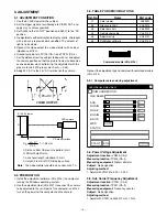
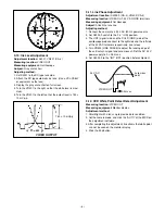
3-9. Hue and Chroma Adjustment
Adjustment location:
S3002-8 (CA-3), computer screen
Measuring location:
VIDEO OUT
Measuring equipment:
Oscilloscope, Vectorscope
Subject:
Color bar chart
1. Display the grayscale chart on full screen.
2. Gradually move the lens aperture from the CLOSE to OPEN
side, and secure the aperture at the point where the AGC
starts to drop from the MAX setting.
3. Shield light with a lens cap, and then remove it.
4. Use the computer’s mouse to adjust each of the R GAIN, B
GAIN, R HUE and B HUE until the luminescent spot repre-
senting red is aligned with the [R] position on the vectorscope
and the luminescent spot representing yellow is aligned with
the [YL] position on the vectorscope.
5. Set the S3002 (white balance switch) to the “ATW” (OFF)
position.
3-6. 28 MHz VCO Voltage ADJUSTMENT
Adjustment location:
CT232 (CA-2)
Measuring location:
TP232 (CA-2)
Measuring equipment:
Digital voltmeter
Subject:
No designation
Adjusting method:
1. Adjust with CT232 to 8.0
±
0.2 Vp-p.
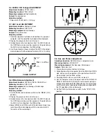
3-7. AGC Level ADJUSTMENT
Adjustment location:
Computer screen
Measuring location:
VIDEO OUT
Measuring equipment:
Oscilloscope
Subject:
Gray scale chart
Adjusting method:
1. Click the adjustment software installed from the personal
computer, and the adjustment window will be displayed.
2. Display the grayscale chart on full screen.
3. Gradually move the lens aperture from the CLOSE side to
the OPEN side, and secure the aperture at the point where
the AGC starts to drop from the MAX setting.
4. Use the computer’s mouse to adjust the AGC in the adjust-
ment window so that the video out terminal is 750
±
10 mVp-p.
3-8. White Balance Adjustment
Adjustment location:
S3002-8, VR302, VR303 (CA-3)
Measuring location:
VIDEO OUT
Measuring equipment:
Oscilloscope, Vectorscope
Subject:
Color bar chart
Adjusting method:
1. Set the S3002 (white balance swtich) to the “MANU” (ON)
position.
2. Display the grayscale chart on full screen.
3. Gradually move the lens aperture from the CLOSE side to
the OPEN side, and secure the aperture at the point where
the AGC starts to drop from the MAX setting.
4. Adjust VR302 and VR303 so that the luminescent spot rep-
resenting white is overlapping with the crosshair mark in
the center of the vectorscope.
VIDEO OUTPUT
10
45
µ
sec
45
µ
sec
R
YL
MG
Cy
G
B
75%
100%
cy
g
yl
mg
b
U
v
W
Содержание VCC-6594P
Страница 12: ...Oct 01 SANYO Electric Co Ltd Osaka Japan ...
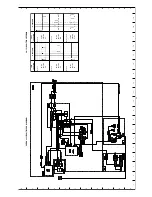
Страница 17: ...A B C D E F G H I J K 1 2 3 4 5 6 7 8 9 10 11 12 13 14 15 16 17 18 19 A B C D E F G H I J K C3 CA 1 CIRCUIT ...
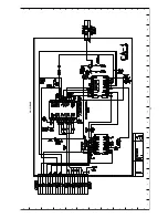
Страница 19: ...A B C D E F G H I J K 1 2 3 4 5 6 7 8 9 10 11 12 13 14 15 16 17 18 19 A B C D E F G H I J K C5 CA 2 CIRCUIT ...
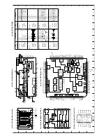
Страница 21: ...A B C D E F G H I J K 1 2 3 4 5 6 7 8 9 10 11 12 13 14 15 16 17 18 19 A B C D E F G H I J K C7 CA 4 CIRCUIT ...

