– 2 –
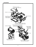
1. DISASSEMBLY
1. Loosen the two screws,
and then remove the left
and right side panels.
2. Remove the rear panel.
3. Remove the two screws,
and then pull out the top cabinet.
4. Remove the two screws, and then remove
the bracket and pull out the bottom cabinet.
5. Remove the front panel.
7. Remove the four screws, and then
disconnect the connector.
8. Remove the five screws, then remove
the CA-2/CA-3 board assemblies and
the FPC, and disconnect the connector.
9. Remove the five screws, and then
remove the lens mount bracket.
10. Remove the two
screws, and then
remove the CA-1
board assembly.
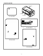
CA-3
board
CA-4 board
CA-2 board
CA-1 board
6. Remove the connector.
Содержание VCC-6594P
Страница 12: ...Oct 01 SANYO Electric Co Ltd Osaka Japan ...
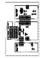
Страница 17: ...A B C D E F G H I J K 1 2 3 4 5 6 7 8 9 10 11 12 13 14 15 16 17 18 19 A B C D E F G H I J K C3 CA 1 CIRCUIT ...
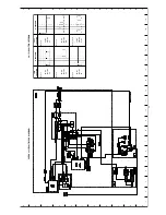
Страница 19: ...A B C D E F G H I J K 1 2 3 4 5 6 7 8 9 10 11 12 13 14 15 16 17 18 19 A B C D E F G H I J K C5 CA 2 CIRCUIT ...
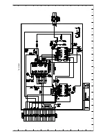
Страница 21: ...A B C D E F G H I J K 1 2 3 4 5 6 7 8 9 10 11 12 13 14 15 16 17 18 19 A B C D E F G H I J K C7 CA 4 CIRCUIT ...

