


LOCATIONS OF CONTROLS AND INDICATORS
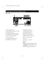
Back Panel
1
Battery compartment cover
2
EXT TIMER IN (external timer input) terminal
3
COM (common) terminal
4
WARNING OUT (warning output) terminal
5
TAPE END OUT (tape end output) terminal
6
SW OUT (switch output) terminal
7
COM (common) terminal
8
ALARM OUT (alarm output) terminal
9
ALARM IN (alarm input) terminal
F
VIDEO IN (video input) jack
G
VIDEO OUT (video output) jack
H
AUDIO IN (audio input) jack
I
AUDIO OUT (audio output) jack
J
MIC IN (microphone input) jack
K
REMOTE (remote control input) jack
L
DC 12 V IN “+” input terminal
M
Do not use
N
DC 12 V IN “–” input terminal
O
Fuse cover
NOTES:
•
This terminal board may be damaged by 5 kg-cm or
more torque and using
φ
6 mm-tip or more size
screendrivers.
•
Pay attention to the polarity of the DC 12 V input
terminal (“+”: red screw, “–”: black screw).
AUDIO
VIDEO
OUT
OUT
IN
IN
MIC IN
REMOTE
EXT
TIMER IN COM
WARNING
OUT
TAPE
END OUT
SW
OUT
COM
OUT
IN
ALARM
DC12V IN
PUSH
OPEN
1
2 4 6 8
3 5 7 9
F
G
H
I
J
K
L
M
N
O
NC4QG/U (SRT-612DC GB) Wed. June, 06/2001
6


