background image

7

Compliance

AC Power Cord for the United Kingdom :

This cord is already fitted with a moulded plug incorporating a fuse, the value of which is indicated on the pin face of the
plug.  Should the fuse need to be replaced, an ASTA approved BS 1362 fuse must be used of the same rating, marked thus

.  If the fuse cover is detachable, never use the plug with the cover omitted.  If a replacement fuse cover is required,

ensure it is of the same colour as that visible on the pin face of the plug (i.e. red or orange).  Fuse covers are available from
the Parts Department indicated in your User Instructions.
If the plug supplied is not suitable for your socket outlet, it should be cut off and destroyed.
The end of the flexible cord should be suitably prepared and the correct plug fitted.  (See Over)

WARNING : A PLUG WITH BARED FLEXIBLE CORD IS HAZARDOUS IF ENGAGED IN A LIVE SOCKET
OUTLET.

The Wires in this mains lead are coloured in accordance with the following code:

Green-and-yellow ············ Earth
Blue ································· Neutral
Brown ······························ Live

As the colours of the wires in the mains lead of this apparatus may not correspond with the coloured markings identifying
the terminals in your plug proceed as follows:
The wire which is coloured green-and-yellow must be connected to the terminal in the plug which is marked by the letter E
or by the safety earth symbol 

or coloured green or green-and-yellow.

The wire which is coloured blue must be connected to the terminal which is marked with the letter N or coloured black.
The wire which is coloured brown must be connected to the terminal which is marked with the letter L or coloured red.

WARNING : THIS APPARATUS MUST BE EARTHED.

ASA

The AC Power Cord supplied with this projector meets the requirement for use in the country you purchased it.  

AC Power Cord for the United States and Canada :

AC Power Cord used in the United States and Canada is listed by the Underwriters Laboratories
(UL) and certified by the Canadian Standard Association (CSA).
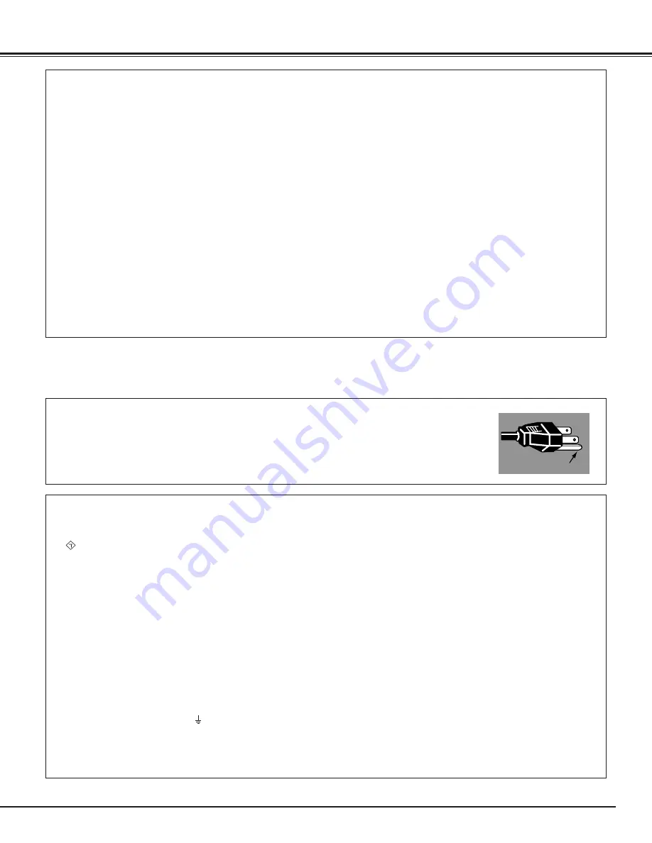
AC Power Cord has a grounding-type AC line plug.  This is a safety feature to be sure that the plug
will fit into the power outlet.  Do not try to defeat this safety feature.  Should you be unable to
insert the plug into the outlet, contact your electrician.

GROUND

THE SOCKET-OUTLET SHOULD BE INSTALLED NEAR THE EQUIPMENT AND EASILY ACCESSIBLE.

AC POWER CORD REQUIREMENT

Federal Communication Commission Notice

Note : This equipment has been tested and found to comply with the limits for a Class B digital device, pursuant to part 15 of
the FCC Rules.  These limits are designed to provide reasonable protection against harmful interference in a residential
installation.  This equipment generates, uses and can radiate radio frequency energy and, if not installed and used in
accordance with the instructions, may cause harmful interference to radio communications.  However, there is no guarantee
that interference will not occur in a particular installation.  If this equipment does cause harmful interference to radio or
television reception, which can be determined by turning the equipment off and on, the user is encouraged to try to correct the
interference by one or more of the following measures :

– Reorient or relocate the receiving  antenna.
– Increase the separation between the equipment and receiver.
– Connect the equipment into an outlet on a circuit different from that to which the receiver is connected.
– Consult the dealer or an experienced radio/TV technician for help.

Use of shielded cable is required to comply with class B limits in Subpart B of Part 15 of FCC Rules.

Do not make any changes or modifications to the equipment unless otherwise specified in the instructions.  If such changes or
modifications should be made, you could be required to stop operation of the equipment.

Model Numbers 

: PLV-Z3

Trade Name 

: Sanyo

Responsible party 

: SANYO FISHER COMPANY

Address 

: 21605 Plummer Street, Chatsworth, California 91311

Telephone No. 

: (818)998-7322

Содержание PLV-Z3

Страница 1: ...Multimedia Projector MODEL PLV Z3 Owner s Manual ...

Страница 2: ...ver you want to with the MY PICTURE MY P button on the remote control See page 11 21 42 Lamp Mode Brightness of the projection lamp can be changed by setting The projector has the function to adjust the brightness according to an input signal for the best suit ed image See page 29 39 Short Zoom Lens This projector is equipped with Short Zoom Lens which allows you to enjoy 100 screen size in range ...

Страница 3: ...er 18 Turning On the Projector 19 Turning Off the Projector 19 Zoom Adjustment 20 Focus Adjustment 20 Keystone Adjustment 21 My Picture Function 21 No Show Function 21 On Screen Menu 22 Menus 23 Input Source Selection Video S Video Component1 2 HDMI 24 Video System Selection 26 Image Level Selection 27 Image Level Adjustment 28 Screen Size Adjustment 30 Input Source Selection 32 Computer System Se...

Страница 4: ...DUCE THE RISK OF FIRE OR ELECTRIC SHOCK DO NOT EXPOSE THIS APPLIANCE TO RAIN OR MOISTURE This projector produces intense light from the projection lens Do not stare directly into the lens as possible Eye damage could result Be especially careful that children do not stare directly into the beam Install the projector in a proper position If not it may result in a fire hazard Provide appropriate spa...

Страница 5: ...ltage points or short out parts that could result in a fire or electric shock Never spill liquid of any kind on the projector Do not install the projector near the ventilation duct of air conditioning equipment This projector should be operated only from the type of power source indicated on the marking label If you are not sure of the type of power supplied consult your authorized dealer or local...

Страница 6: ...r properly Improper Installation may reduce the lamp lifetime and cause a fire hazard NO DOWNWARD NO SIDEWARD Installing the Projector in Proper Position Openings in the cabinet are provided for ventilation and to ensure reliable operation of the product and to protect it from overheating and these openings must not be blocked or covered CAUTION Hot air is exhausted from the exhaust vent When usin...

Страница 7: ...da is listed by the Underwriters Laboratories UL and certified by the Canadian Standard Association CSA AC Power Cord has a grounding type AC line plug This is a safety feature to be sure that the plug will fit into the power outlet Do not try to defeat this safety feature Should you be unable to insert the plug into the outlet contact your electrician GROUND THE SOCKET OUTLET SHOULD BE INSTALLED ...

Страница 8: ...rminals and Connectors q Exhaust Vent CAUTION Hot air is exhausted from the exhaust vent Do not put heat sensitive objects near this side Front q w e r t u y i 0 w Air Intake Vent The two arrows show air flow e Top Controls and Indicators r Front Cover t Infrared Remote Receiver y Projection Lens u Zoom Lever i Focus Ring o Lens Shift Ring Up Down 0 Lens Shift Ring Left Right 9 o Part Names and Fu...

Страница 9: ...ely q COMPUTER Connect computer output or RGB Scart 21 pin video output to this connector p17 18 Terminal q w t e t VIDEO Connect the composite video output from video equipment to this jack p16 r COMPONENT 1 2 Connect the component video output to these jacks p16 e S VIDEO Connect the S Video output from video equipment to this jack p16 w SERVICE PORT This jack is used to service this projector r...

Страница 10: ...ojector gets ready to be turned on It lights red when the projector is in the stand by mode It remains green while the projector is under operation When the front cover is closed it lights orange y POINT Upe Downd Left7 Right8 button Selects an item or adjusts value in the On Screen Menu These are also used to pan the image in the Digital zoom mode p40 u SELECT button Executes the item selected It...

Страница 11: ...Level p27 37 0 SELECT button Executes the item selected or to expand or compress image in the Digital zoom mode p40 q LIGHT button Lights the buttons on the remote control for about 10 seconds 0 r 3 u t INPUT buttons Selects input source p24 32 5 MY PICTURE button Displays the captured image p21 42 y KEYSTONE buttons Corrects keystone distortion p21 41 1 IMAGE ADJ button Displays the On Screen Men...

Страница 12: ... batteries according to the instructions Point the remote control toward the projector Infrared Remote Receiver whenever pressing any button Maximum operating range for the remote control is about 16 4 5m and 60 in front of the projector 16 4 5 m 60 Remote Control Batteries Installation Remote Control Operating Range Pull up the lid and remove it Remove the battery compartment lid Slide the batter...

Страница 13: ... should be taken See page 6 Adjustable Feet NOTE The brightness in a room has a great influence on picture quality It is recommended to limit ambient lighting in order to provide the best image The values shown are approximate and may vary from the actual size This projector is designed to project on a flat projection surface and can be focused from 3 9 1 2m 20 0 6 1m Refer to the figure and the t...

Страница 14: ...ed neutral conductor To reduce risk of electrical shock do not plug into any other type of power system Consult your authorized dealer or service station if you are not sure of the type of power being supplied Connect the projector with all peripheral equipment before turning the projector on See page 16 18 for connection CAUTION For safety unplug AC power cord when the projector is not in use Whe...

Страница 15: ...htward Turn the lens shift ring up down up down to move the lens upward downward Lens Shift Ring Up Down V V W 1 2W downmost leftmost rightmost Lens Shift Up Down Lens Shift Left Right Moving the Lens NOTE The best image is generally obtained at the center of the lens shift When using the lens shift upward or downward to the limit the lens does not move to the limit leftward or rightward When usin...

Страница 16: ...lied NOTE When connecting the cable the power cords of both the projector and the external equipment should be disconnected from AC outlet COMPU COMPUTER COMPONENT COMPONENT 1 2 HDMI Video Equipment Component Video Output Y Pb Cb Pr Cr Component Component Use a component cable option Connecting to Video Equipment Component Component Cable RCA x 3 NOTE See page 59 for ordering optional cables Conne...

Страница 17: ...put Scart VGA Cable COMPUTER COMPUTER COMPONENT COMPONENT 1 2 HDMI HDMI Video Equipment HDMI HDMI Cable HDMI Use a HDMI cable option for HDMI Connecting to Video Equipment HDMI HDMI Video Output NOTE When connecting the cable the power cords of both the projector and the external equipment should be disconnected from AC outlet NOTE See page 59 for ordering optional cables ...

Страница 18: ...Connecting to a Computer Computer Analog Use a VGA cable option or a DVI VGA cable commercially available VGA Cable NOTE See page 59 for ordering optional cables NOTE When connecting the cable the power cords of both the projector and the external equipment should be disconnected from AC outlet DVI VGA Cable ...

Страница 19: ...ULT IN SHORTENING LAMP LIFE 1 3 When the projector has cooled down enough to be turned on again the POWER indicator lights red Then you can turn the Main On Off switch off and disconnect the AC power cord The message disappears after 4 seconds 4 After the count down the input source that was selected last and the Lamp mode status icon appear on the screen Turning Off the Projector NOTE When the fr...

Страница 20: ...20 Basic Operation Focus Adjustment Move the Zoom Lever to zoom in and out Rotate the Focus Ring to adjust the projected picture focus Zoom Lever Focus Ring Zoom Adjustment ...

Страница 21: ...YSTONE button or the Point Up button Reduce the lower width with the KEYSTONE button or the Point Down button 1 Press the KEYSTONE button on the remote control or select the Keystone in the Setting Menu p41 The Keystone dialog box appears 2 Correct keystone distortion by pressing the KEYSTONE button or the Point Up Down button Press the KEYSTONE button or the Point Up button to reduce the upper pa...

Страница 22: ...ton once then you will go back to the previous screen Or press CANCEL button twice the On Screen Menu will be closed Select an item by pressing the Point Up Down button and activate the item that you have selected with the SELECT Point Left or Point Right button 1 2 4 3 You can control and adjust this projector through the On Screen Menu Refer to the following pages to operate each adjustment on t...

Страница 23: ...re Mounting Rear Power management Power off confirmation Remote control Lamp counter reset Factory default Cleaning Panel adjustment p41 44 Input Menu selects input source p32 PC System Menu selects computer system p33 Image Select Menu selects image level from Creative cinema Pure cinema Natural Video Dynamic Powerful Graphic User Image 1 4 p37 Image Adjust Menu adjusts Contrast Brightness Color ...

Страница 24: ...e remote control according to video input SCREEN IMAGE ADJ SELECT USER SETTING MY PICTURE COMPO 1 COMPO 2 LAMP MODE CLEAR DARK U 1 U 2 U 3 U 4 LAMP S VIDEO VIDEO C 1 C 2 HDMI PC Remote Control INPUT buttons INPUT buttons VIDEO S VIDEO COMPO 1 COMPO 2 HDMI When video input signal is connected to the VIDEO jack select Video VIDEO When video input signal is connected to the S VIDEO jack select S vide...

Страница 25: ...then press SELECT button 1 2 When video input signal is connected to the VIDEO jack select Video Video When video input signal is connected to the S VIDEO jack select S video S Video Menu Operation Input Source When video input signal is connected to the Y Pb Cb Pr Cr jacks select Component 1 2 COMPONENT 1 2 When video input signal is connected to the HDMI termi nal select HDMI HDMI ...

Страница 26: ...PAL M PAL N The projector automatically detects incoming video signal and adjusts itself to optimize its performance If the projector cannot reproduce proper video image it is necessary to select a specific component video signal format among 480i 575i 480p 575p 720p 1035i and 1080i Auto Component Video Signal Format Video or S Video Component The projector automatically detects incoming video sys...

Страница 27: ... Selection Direct Operation Menu Operation MENU CANCEL SCREEN IMAGE ADJ SELECT USER SETTING COMPO 1 COMPO 2 CLEAR DARK U 1 U 2 U 3 U 4 S VIDEO VIDEO C 1 C 2 HDMI Remote Control IMAGE buttons To enjoy contrasting 3D images in a dark room Creative cinema To enjoy images with quiet tone of colors without excess gradation in a dark room Pure cinema User preset images in the Image Adjust Menu p28 29 Us...

Страница 28: ...e Green Press the Point Left button to lighten blue tone and the Point Right button to deepen blue tone From 31 to 31 White balance Blue NOTE Tint cannot be selected when the video system is PAL SECAM PAL M or PAL N except for 575i Color and Tint cannot be selected when the input source is HDMI After adjusting any of the White balance Red Green or Blue the Color temp display will change to User Im...

Страница 29: ...f 4 image levels with the Point Up Down button and press the SELECT button A confirmation box will appear and select Yes Resets adjustments to their factory default settings Reset Store Interlace video signal can be converted to a progressive signal Off Not activated L1 Select L1 for an active picture L2 Select L2 for a still picture Progressive This function can be selected only when Advanced men...

Страница 30: ...nu to provide better quality Full Screen Size Adjustment Provides an image to fit the screen size 16 9 aspect ratio by expanding the width and height of the image uniformly This function can be used to project a letter box mode picture 4 3 aspect picture with black bar on the top and bottom edges at a wide video aspect ratio of 16 9 Zoom Provides an image including a caption to fit the screen size...

Страница 31: ...ected image is small Normal through Modifies an image of 4 3 aspect ratio to fit the screen size 16 9 aspect ratio It expands the width and height of the image and makes it look natural Natural wide 1 Normal through Naturalwide1 When the signal is 16 9 modifies an image of 4 3 aspect ratio to fit the screen size 16 9 aspect ratio It expands the width and height of the image and makes it look natur...

Страница 32: ...u want to select and then press the SELECT button 3 When the input terminal is Scart with a DVD player connected to the COMPUTER terminal select RGB Scart RGB Scart When the input source is analog coming from a computer connected to the COMPUTER terminal select RGB Analog RGB Analog Input Source Selection Direct Operation Menu Operation Input Menu Source Selection Menu pointer Closes the source se...

Страница 33: ...sage Auto is displayed in the PC System Menu icon When the image is not provided properly manual adjustment is required p35 36 There is no signal input from the connected computer Check the connection of the computer and see if the projector is set correctly See Troubleshooting on page 52 Auto PC System Menu Select the PC System Menu with the Point Up Down button and then press the Point Right but...

Страница 34: ...tore adjustment data Adjustment parameters from Auto PC adjustment can be memorized in this projector Once parameters are memorized the setting can be done just by selecting Mode in the PC System Menu p33 See Store on page 36 NOTE The Auto PC adjust cannot be operated when 480i 575i 480p 575p 720p HDTV 1035i HDTV or 1080i HDTV is selected in the PC System Menu Computer Adjustment Auto Automaticall...

Страница 35: ...nt Left Right button to adjust value From 0 to 31 Fine sync Adjusts the number of total dots in one horizontal period Press the Point Left Right button and adjust number to match your PC image Total dots Adjusts horizontal picture position Press the Point Left Right button to adjust the position Horizontal Adjusts vertical picture position Press the Point Left Right button to adjust the position V...

Страница 36: ...s Mode free Vacant Mode Shows values of Total dots Horizontal Vertical Display area H and Display area V Closes this dialog box To store adjustment data To clear adjustment data To clear adjustment data previously set select Mode free and press the Point Right button A dialog box will appear and choose one of 5 modes and then press the SELECT button This Mode has parameters being stored NOTE Displ...

Страница 37: ...l or Graphic can be selected These levels are suitable for a bright room Direct Operation Menu Operation MENU CANCEL SCREEN IMAGE ADJ SELECT USER SETTING COMPO 1 COMPO 2 CLEAR DARK U 1 U 2 U 3 U 4 S VIDEO VIDEO C 1 C 2 HDMI Remote Control IMAGE buttons To enjoy contrasting 3D images in a dark room Creative cinema To enjoy images with quiet tone of colors without excess gradation in a dark room Pur...

Страница 38: ...Press the Point Left button to lighten green tone and the Point Right button to deepen green tone From 31 to 31 White balance Green Press the Point Left button to lighten blue tone and the Point Right button to deepen blue tone From 31 to 31 White balance Blue Press the Point Left Right button for Color temperature level that you want to select High Mid Low1 Low2 Low3 Color temp Image Adjust Menu ...

Страница 39: ...el Menu will appear Choose one of 4 image levels with the Point Up Down button and press the SELECT button A confirma tion box will appear and select Yes Press the Point Right button at this icon to store the value This arrow indicates that there are previous items Select this item and press the Point Up button to go to the previous item Direct Operation with Remote control Pressing the LAMP butto...

Страница 40: ...isplay any resolution higher than 1280 X 720 If your computer s screen resolution is higher than 1280 X 720 reset the resolution to the lower before connecting to the projector The image data in other than the resolution 1280 x 720 is modified to fit the screen size in initial mode The panning function may not operate properly if the computer system prepared in the PC Adjust Menu is used Provides ...

Страница 41: ...ge 21 Setting Menu position Background color This function is used to change the color of background in the On Screen Menu Default background color Background color is grayish and half transparent Background color is blackish and half transparent Background color is transparent Menu position This function is used to change the position of the On Screen Menu Move it with the Point Up Down Left Righ...

Страница 42: ... the middle press CANCEL button Capture NOTE A signal from a computer can be captured up to XGA 1024 x 768 If selecting 1280 x 1024 at Display area in the PC Adjust Menu p36 then the image cannot be captured A signal from video equipment can be captured except for 720p 1035i 1080i When capturing the image that has been adjusted by the Keystone function the adjustment data is automatically reset an...

Страница 43: ... more When the input signal is interrupted and no button is pressed for 30 seconds or more the timer display with the message No signal appears on the screen The count down starts for 5 minutes When the count down time has elapsed the lamp will be turned off to cool itself down The POWER indicator is flashing red during this cooling off period The next performance depends on setting as follows On ...

Страница 44: ...ing operation Panel adjustment This function is used to get the best picture reproduction of each of the R red G green and B blue LCD panels If proper adjustment is not made you might get vertical noise lines on the screen This function should be made about ten minutes after turning on the projector with any signals or without a signal Darker environment makes your adjustment more accurate The Tes...

Страница 45: ...id you provide appropriate space for the projector to be ventilated Check the installing condition to see if ventilation slots are not blocked Is the projector not installed near the ventilation duct of air conditioning equipment which may be hot Install the projector away from the ventilation duct of air conditioning equipment Is the air filter clean Clean the air filter or replace it with a new ...

Страница 46: ...pull the hole cover strongly Do not look into the holes Strong light could damage your eyes Do not look into Air intake vent and Exhaust vent either Use the blower and the nozzle only to clean the projector Do not try to use them to another purpose Do not use the blower and nozzle to a man especially eyes mouth or ear and so on Be careful not children put the blower and nozzle into their mouths or...

Страница 47: ...topped by the stoppers when being put in the hole Do not try to force the nozzle into further The nozzle could be break and fall into inside of the projector Inside Outside Do not open the bottom cover except for when you clean the inside of the projector Especially while operating the projector the optical parts could damage Which hole to put the nozzle in When you look at the screen When red spo...

Страница 48: ...above symptoms are noticed contact your authorized dealer or service station for proper cleaning Cleaning the Air Filter Air Filter 2 Air Intake Vent Air Filter 1 Intake Vent Latch Air Filter 2 Pull the latches on both edges upward 3 Remove dust and dirt with a soft brush or vacuum cleaner Be careful not to damage the air filters and do not clean the air filters with water When there is much dust ...

Страница 49: ...d scratches 3 Softly wipe the projection lens with a cleaning cloth that con tains a small amount of non abrasive camera lens cleaner or use lens cleaning paper or a commercially available air blower to clean the lens Avoid using an excessive amount of cleaner Abrasive cleaners solvents or other harsh chemicals might scratch the surface After removing the air filter from the projector as described...

Страница 50: ... cool for at least 45 minutes before you open the Lamp cover The inside of the projector can become very hot POWER WARNING LAMP REPLACE This indicator lights yellow when the life of the projection lamp draws to an end Top Control CAUTION Screw Screw Turn off the projector and disconnect the AC plug Allow the projector to cool for at least 45 minutes Loosen 2 screws of the lamp with a screwdriver a...

Страница 51: ...the instructions in the Lamp Replacement section of this manual Continuous use of the lamp with the LAMP REPLACE indicator lighted may increase the risk of lamp explosion A Lamp may explode as a result of vibration shock or degradation as a result of hours of use as its lifetime draws to an end Risk of explosion may differ according to the environment or conditions in which the projector and lamp ...

Страница 52: ...he projector OFF and wait until condensation disappears Image is Left Right reversed Check the Mounting Rear item See Setting on page 42 Problem Try these solutions Image is Top Bottom reversed Check the Mounting item See Setting on page 42 Some displays are not seen during the Operation Check the Display item See Setting on page 41 No image Check the connection between video equipment or your com...

Страница 53: ...WARNING indicator keeps flashing Check and clean the Air filter Projector Condition The projector is ready to be turned on with the POWER ON OFF button POWER red green orange Indicators LAMP REPLACE yellow WARNING red The projector detects an abnormal condition and cannot be turned on Unplug the AC power cord and plug it again to turn on the projector If the projector is turned off again disconnec...

Страница 54: ...tem 2 User image 4 Lamp mode Screen Film Computer Go to System 4 HDMI Go to System 3 Computer N A RGB Analog RGB Scart Selected system System 3 Video Dynamic Powerful Graphic Advanced menu 31 31 31 31 31 31 31 31 31 31 31 31 High Mid Low 1 Low 3 Low 2 Off 31 31 7 7 7 7 L1 L2 Bright mode On Off Iris React image mode 1 React image mode 2 Theater black mode User image 1 User image 2 User image 3 User...

Страница 55: ... Store Normal Full True Digital zoom 0 31 31 31 31 31 Computer Input PC Adjust 640 x 480 720 x 400 800 x 600 1024 x 768 1152 x 864 1280 x 720 1280 x 1024 Mode 1 Mode 2 Mode 3 Mode 4 Mode 5 Image Select High 31 31 31 31 31 31 7 7 User image 1 User image 2 User image 3 User image 4 Screen Quit Quit Yes No Systems displayed in the System Menu vary depending on an input signal Mid Reset Yes No Low 1 L...

Страница 56: ... 08 MAC 21 1152 x 870 68 68 75 06 XGA 11 1024 x 768 XGA 12 1024 x 768 XGA 13 1024 x 768 XGA 14 1024 x 768 61 00 75 70 XGA 15 1024 x 768 35 522 86 96 Interlace 46 90 58 20 47 00 58 30 58 03 72 00 SXGA 1 1152 x 864 64 20 70 40 SXGA 11 1152 x 900 SXGA 13 1280 x 1024 SXGA 14 1280 x 1024 61 20 65 20 50 00 86 00 Interlace 720p 50 00 94 00 Interlace 45 00 60 00 SXGA 17 1152 x 900 SXGA 18 1280 x 1024 61 8...

Страница 57: ...uter Input Terminal HDMI terminal 19 pin x 1 HDMI Input Terminal 0 to 11 8 Feet Adjustment Power Source AA UM3 or LR06 1 5V ALKALINE Type x 2 Operating Range 16 4 5m 30 Dimensions 1 97 x 1 06 x 6 61 50mm x 27mm x 168mm Net Weight 4 4oz 126g including batteries Remote Control 480i 480p 575i 575p 720p 1035i and 1080i High Definition TV Signal AC 100 120 V 2 4 A Max Ampere 50 60 Hz The U S A and Cana...

Страница 58: ...58 Appendix Dimensions POWER WARNING LAMP REPLACE MENU INPUT SELECT ON OFF 14 13 359 10 77 273 5 Unit inch mm 11 8 Max 4 59 116 7 4 52 114 7 2 68 68 ...

Страница 59: ...rminal VGA Red R Cr Input Output Ground Horiz sync Green G Y Input Output Blue B Cb Input Output Ground Red Ground Green Ground Blue 1 5 2 4 3 6 7 8 Horiz sync Input Output Composite H V sync Ground Vert sync Ground Vert sync 9 13 10 12 11 14 15 1 3 5 7 9 11 13 15 17 19 18 16 14 12 10 8 6 4 2 TMDS Data 2 Input Ground TMDS Data 1 Ground TMDS Data 2 TMDS Data 1 Input TMDS Data 2 Input TMDS Data 1 In...

Страница 60: ...Printed in Japan Part No 610 317 4693 1AA6P1P4651 M4SA SANYO Electric Co Ltd ...

Отзывы: