


-25-
Adjustments
v
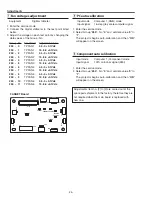
Color index adjustment-1
Condition
Dark room
Input mode
Computer 1 (RGB) mode
Image mode
Dynamic
Input signal
RGBW-Ramp pattern (Internal sig-
nal)
1. Enter the service mode.
2. Select Group "
151
", No. "
21
" and set data value to
"
1
". The RGBW-Ramp internal pattern is displayed on
the screen.
3. Select Group "
151
", No. "
0
" and set data value to the
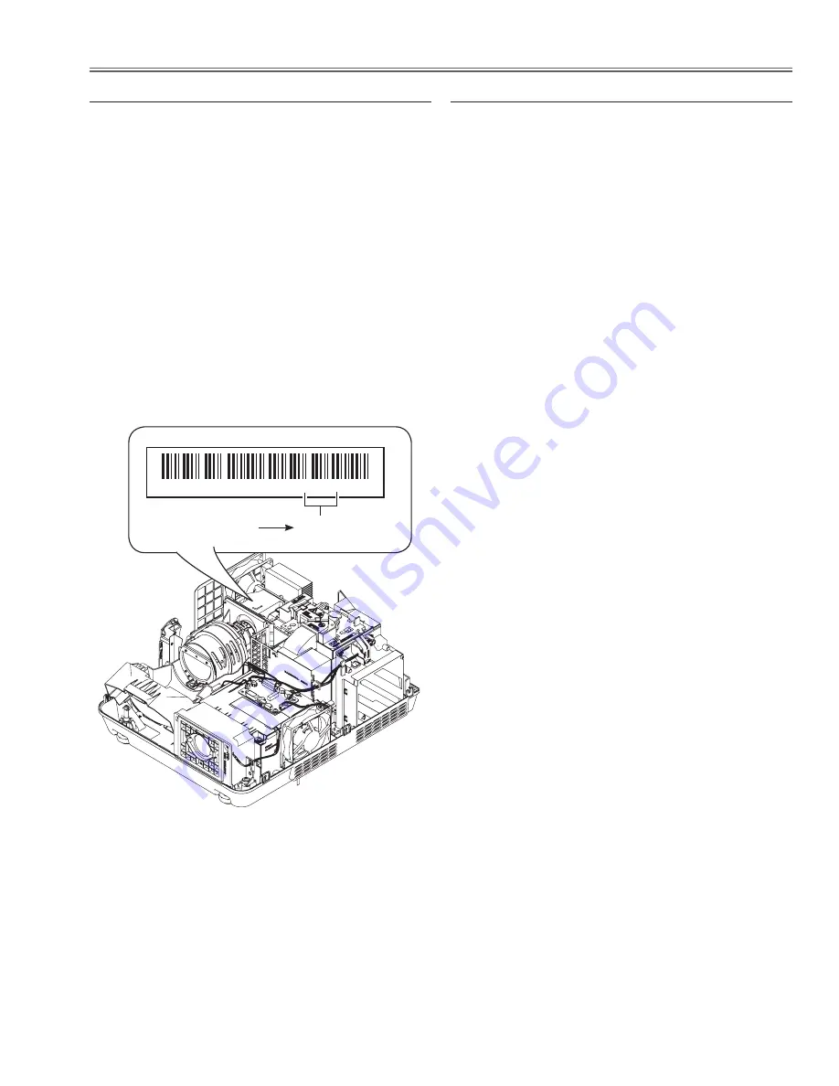
specified index value which is printed on the label of
the optical unit.
4. Check that the proper gradation color image is repro-
duced on the screen.
* Only this adjustment is needed when the optical unit or
main board is replaced.
b
Color index adjustment-2
Condition
Dark room
Input mode
Computer 1 (RGB) mode
Image mode
Dynamic
Input signal
RGBW-Ramp pattern (Internal sig-
nal)
1. Enter the service mode.
2. Select Group "
151
", No. "
21
" and set data value to
"
1
". The RGBW-Ramp internal pattern is displayed on
the screen.
3. Select Group "
151
", No. "
0
" and change data value to
obtain the proper gradation color image is reproduced
on the screen
* Only this adjustment is needed when the color wheel
is replaced.
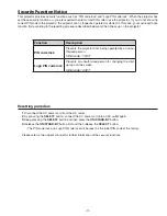
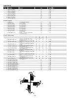
�
9 0 0 0 0 0 0 0 0 2 W 0 7 0
�
“ 0 7 0 ”
3-digit index value
Label on the optical unit
Содержание PDG-DXL2000E
Страница 47: ... 47 IC Block Diagrams LV49152V Audio output IC001 LC87F2G08A Sub micom IC4501 ...
Страница 48: ... 48 IC Block Diagrams M62393 DAC IC7881 MR4010 Power switching IC631 ...
Страница 49: ... 49 IC Block Diagrams PIC18F67J60 Network IC8301 NJW1156 Audio selector IC5101 ...
Страница 82: ...Key No Part No Description Key No Part No Description Electrical Parts List 82 KV2 DXL2000E00 ...
Страница 83: ...Key No Part No Description Key No Part No Description 83 Electrical Parts List KV2 DXL2000E00 ...
Страница 84: ... KV2AC Apr 2011 DC 50 Printed in Japan SANYO Electric Co Ltd ...