manualshive.com logo in svg
background image

1. SERVICE TOOLS ........................... 2

2. AN OVERVIEW OF THE

MECHANISM .................................. 3

2-1. Exploded view of the Unit .................. 3

2-2. Overview ............................................ 5

2-3. Cam Drive .......................................... 5

2-4. Paper Advance Drive ......................... 6

2-5. Ink Ribbon Drive ................................ 7

2-6. Mechanism Mode Verification

Method ............................................... 7

3. DISASSEMBLING THE MAIN

PARTS OF THE MECHANISM ....... 8

3-1. “MOTOR,FAN DC 1.8W”, “GUIDE,

INK-SVF01/EX”, and “LEVER,
CASSETTE STOPPER” .................... 8

3-2. S REEL ASSEMBLY .......................... 9

3-3. HEAD ............................................... 10

3-4. PAPER EXIT ROLLER .................... 12

3-5. SUPPLY PAPER ROLLER .............. 12

3-6. “ASSY, MOTOR STEPPING” ........... 14

Contents

3-7. RELAY PULLEY .............................. 14

3-8. “PULLEY,DRUM” ............................. 16

3-9. CAM MOTOR .................................. 16

3-10. “CHASSIS,SUB LOWER” ................ 18

3-11. “COMPL,HOLDER,PINCH SIDE”,

“COMPL,HOLDER,PINCH PICK”,
“COMPL,HOLDER,PINCH EXIT F”,
and “COMPL,HOLDER,PINCH
EXIT” ............................................... 18

3-12. “SLIDE,LEVER TPH” ....................... 20

3-13. “HOUSING,MOTOR FAN” and

“COMPL PWB,MC-6” ....................... 20

3-14. “ASSY,CHASSIS R”, “COMPL, PIPE

DRUM RUBBER”, “COMPL,GUIDE,
PAPER”, “CAM,MECHANISM R”,
and “CAM,MECHANISM L” ............. 22

3-15. “GUIDE,CASSETTE R” and

“COMPL PWB,MC-3” ....................... 24

3-16. “GUIDE,PAPER EXIT”, “COMPL

PWB,MC-4”, and “COMPL PWB,
MC-5” ............................................... 24

3-17. “LEVER,TPH ADJUST”, “BEARING,

DRUM”, and “BEARING,DRUM” ..... 25

4. TROUBLESHOOTING .................. 26

4-1. The mechanism malfunctions when

the power is turned on. .................... 26

4-2. Poor printing quality ......................... 26

4-3. Not printing ...................................... 27

4-4. Paper stopping ................................ 28
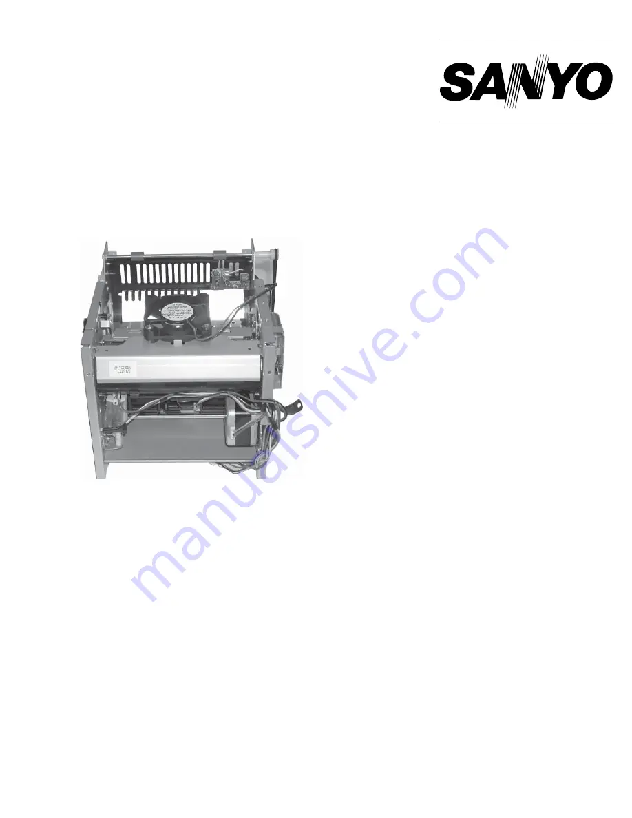
MECHANISM SERVICE
TECHNICAL INFORMATION

Digital Photo Printer

FILE NO.

REFERENCE No.MM5310544

SVF01/EX, U, C

DVP-P1EX

(Product code: 126 306 02)

DVP-P1

(Product code: 126 306 01)

DVP-P1C

(Product code: 126 306 03)

Содержание DVP-P1

Страница 1: ...MPL HOLDER PINCH PICK COMPL HOLDER PINCH EXIT F and COMPL HOLDER PINCH EXIT 18 3 12 SLIDE LEVER TPH 20 3 13 HOUSING MOTOR FAN and COMPL PWB MC 6 20 3 14 ASSY CHASSIS R COMPL PIPE DRUM RUBBER COMPL GUIDE PAPER CAM MECHANISM R and CAM MECHANISM L 22 3 15 GUIDE CASSETTE R and COMPL PWB MC 3 24 3 16 GUIDE PAPER EXIT COMPL PWB MC 4 and COMPL PWB MC 5 24 3 17 LEVER TPH ADJUST BEARING DRUM and BEARING DR...

Страница 2: ...226 VJ8 0227 No 2 3 VJ8 0228 No 4 VJ8 0229 No 5 VHJ 0099 No 6 No Jig No Quantity Parts name 1 VJ8 0225 1 Lever TPH adjusting tool 2 VJ8 0226 1 Dial tension gauge 3 VJ8 0227 1 Dial tension gauge 4 VJ8 0228 1 Ruler 5 VJ8 0229 1 Grease 6 VHJ 0099 1 Oil ...

Страница 3: ...X0 25 4D000 1 SPRING PRESSURE DRUM 4E000 1 SHAFT PULLEY FIX 4F000 1 PULLEY DRUM 4G100 1 ASSY LEVER PULLEY 4G200 1 PULLEY RELAY DRUM 4G300 1 STOPPER BELT DRUM 4G400 1 SPECIAL WAHSER 3X0 5 4H000 1 SPECIAL SCREW 2 6X8 4I000 1 BELT DRUM 4J000 1 BELT MOTOR STEP Loc No Quantity Parts name 4N000 1 SCR S TPG BIN 2 6X3 5C000 1 SPECIAL WASHER 1 5X0 5 5F000 1 SPRING PINCH ROLLER F 5H000 1 SPRING PINCH ROLLER...

Страница 4: ...PG BIN 2 6X4 4A000 1 COMPL PIPE DRUM RUBBER 4B000 1 SPECIAL WASHER 7 1X0 8 4K000 1 ASSY MOTOR STEPPING 4L000 2 NUT HEX 3 4M000 4 GASKET O RING D2 8 4P000 1 SPECIAL WASHER 4X0 3 5A000 1 COMPL HOLDER PINCH SIDE 5B000 1 COMPL HOLDER PINCH EXIT 5C000 1 SPECIAL WASHER 1 5X0 5 NOTE Items marked N S P are not supplied Loc No Quantity Parts name 5D000 1 COMPL HOLDER PINCH PICK 5E000 1 COMPL HOLDER PINCH E...

Страница 5: ...OLDER TPH 1A000 The setting of the paper guide COMPL GUIDE PAPER 5I000 and the play of the head COMPL HOLDER TPH 1A000 when under pressure The pressure and release of the non paper exit pinch rollers COMPL HOLDER PINCH SIDE 5A000 COMPL HOLDER PINCH PICK 5D000 and COMPL HOLDER PINCH EXIT F 5E000 The pressure and release of the paper exit pinch roller COMPL HOLDER PINCH EXIT 5B000 The release and co...

Страница 6: ... PICK of the COMPL HOLDER PINCH EXIT 5B000 descends so the printing paper is expelled by the platen COMPL PIPE DRUM RUBBER 4A000 and the paper exit roller ASSY ROLLER EXITGEAR 6C000 ASSY ROLLER EXIT PULLEY 6F000 Ordinarily the stepping motor ASSY MOTOR STEPPING 4K000 revolves in the regular direction counterclockwise when looking at the mechanism from the right The drive for the paper exit rollers...

Страница 7: ...e head COMPL HOLDER TPH 1A000 and the platen COMPL PIPE DRUM RUBBER 4A000 during the yellow printing process they are driven at a set speed by the stepping motor ASSY MOTOR STEPPING 4K000 Upon completion of the Y yellow printing process when the printing paper is returned to the initial position for printing and the ink ribbon is wound to the beginning of the M magenta ribbon The beginning positio...

Страница 8: ...INK SVF01 EX 03800 Refer to Fig 3 1 1 4 Remove portion A on the LEVER CASSETTE STOP PER 3A000 from hole on the ASSY CHASSIS L 7C000 as shown in Fig B of Fig 3 1 2 5 While rotating portion B on the LEVER CASSETTE STOPPER 3A000 upper side remove it from hole on the ASSY CHASSIS L 7C000 Refer to Fig 3 1 2 6 Pull portion C on the LEVER CASSETTE STOPPER 3A000 out from hole on the ASSY CHASSIS L 7C000 a...

Страница 9: ...EXIT 2B000 Refer to Fig 3 2 2 ASSEMBLY NOTES 1 After cleaning shaft 1 apply oil VHJ 0099 around it Refer to Fig 3 2 2 2 Insert portion A on the COMPL HOUSING REEL S 2A000 into hole on the ASSY CHASSIS R 7A000 as shown in Fig A of Fig 3 2 2 3 Align dowel 1 on the ASSY CHASSIS R 7A000 with hole 1 on the COMPL HOUSING REEL S 2A000 Refer to Fig 3 2 2 4 Install the BELT PAPER EXIT 6I000 without bending...

Страница 10: ...ful not to distort the ASSY CHASSIS R and pull portion A out from hole 2 and remove the ASSY LEVER TPH DOWN 1F000 Refer to Fig 3 3 2 9 Disconnect the connector from the COMPL PWB MC 1 MC 1 10 Remove the SCR S TPG BIN 2 6X4 7K000 and remove the COMPL PWB MC 1 MC 1 Refer to Fig 3 3 2 NOTE It is unnecessary to remove the COMPL PWB MC 1 MC 1 to replace the COMPL HOLDER TPH 1A000 ASSEMBLY NOTES 1 Inser...

Страница 11: ...COMPL HOLDER TPH 1A000 the out from hole 4 and remove it Remove shaft 3 in the direction of the arrow as shown in Fig D NOTE Be careful that the ASSY CHASSIS is not transformed Be careful not to touch the surface of the head on the COMPL HOLDER TPH 1A000 7 Remove the SPRING TPH CENTER 1H000 and SPECIAL WASHER 4 2 X 0 3 1J000 ASSEMBLY NOTES 1 After replacing the COMPL HOLDER TPH 1A000 be sure to re...

Страница 12: ... 7A000 ASSEMBLY NOTES 1 Do not injure the rubber roller portions on the ASSY ROLLER EXITGEAR 6C000 andthe ASSY ROLLER EXIT PULLEY 6F000 when installing them into the ASSY CHASSIS 2 Align portion A on the ASSY ROLLER EXIT PULLEY 6F000 and portion B on the ASSY ROLLER EXIT GEAR 6C000 with holes on the ASSY CHASSIS R 7A000 as shown in Fig B of Fig 3 4 3 3 Install the two BEARING SHAFT L 6D000 so that...

Страница 13: ...RELAY PICK UP 6K000 to the ASSY CHASSIS R 7A000 as shown in Fig 3 5 3 At that time be careful that dowel 2 is not placed over the CAM MECHANISM R 5L000 5 Install the SPRING ARM TRAY PAPER 6N000 as shown in Fig D of Fig 3 5 3 6 Insert and hook the long end of the SPRING PINCH RELEASE 5H100 between washer and arm plate and hook the short end onto the GUIDE PAPER PICK 7I000 as shown in Figs A and B o...

Страница 14: ...mm The mea suring position and the direction of pressure on the BELT MOTOR STEP 4J000 are shown in Fig 3 6 3 e If the pressure welding value is not 0 34N 0 15N loosen the NUT HEX 3 4L000 B and fine adjust the ASSY MOTOR STEPPING 4K000 then re tighten the NUT HEX 3 4L000 B again f Repeat steps c d and e above until the pressure welding value is within 0 34N 0 15N SPECIAL WASHER 4X0 3 4P000 NUT HEX ...

Страница 15: ...al Tension Gauge DTN 150G VJ8 0226 until play in the BELT DRUM 4I000 is 1mm The measuring posi tion and the direction of pressure are shown in Fig 3 7 1 d If the pressure welding value is not 1 34N 0 29N loosen the SPECIAL SCREW 2 6X8 4H000 and fine adjust the ASSY LEVER PULLEY 4G100 then re tighten the SPECIAL SCREW 2 6X8 4H000 Repeat steps b and c above until the pressure welding value is within...

Страница 16: ...ion of the arrow A with a screwdriver slide it in the direction of the arrow B and remove as shown in Fig B of Fig 3 9 1 NOTE Be careful that the ASSY CHASSIS L 7C000 is not distorted 7 Remove the ASSY GEAR CAM 5J000 ASSEMBLY NOTES 1 Install the ASSY GEAR CAM 5J000 in the designated position move gear on the ASSY CHASSIS L 7C000 side approximately 5mm in the direction C as shown in Fig H of Fig 3 ...

Страница 17: ...00 Fig A Portion A Arrow B Arrow A Push Hooks on the GUIDE CASSETTE R 3B100 Fig B Worm gear Fig 3 9 1 COMPL MOTOR CAM 6A000 Fig E Fig D Portion A Portion B Portion C Fig C Dowel Dowel Dowel Mechanism Mode Verification Hole Fig 3 9 2 CAM MECHANISM L 5K000 Fig F Portion F Portion E Front side Front side Fig G Fig H ASSY CHASSIS L N S P 7C000 ASSY GEAR CAM 5J000 CAM MECHANISM R 5L000 C D Shaft of the...

Страница 18: ...INCH ROLLER RB 5H000 and the SPRING PINCH ROLLER LB 5G000 Refer to Fig 3 11 1 and Fig 3 11 3 10 Remove the COMPL HOLDER PINCH PICK 5D000 Refer to Fig 3 11 2 11 Remove the COMPL HOLDER PINCH EXIT F 5E000 Refer to Fig 3 11 3 12 Remove the two SPECIAL WASHER 1 5X0 5 5C000 on the both sides and the COMPL HOLDER PINCH EXIT 5B000 Refer to Fig 3 11 3 ASSEMBLY NOTES 1 Install the COMPL HOLDER PINCH EXIT 5...

Страница 19: ...ase VJ8 0229 Fig A Fig B Fig 3 11 1 COMPL HOLDER PINCH SIDE 5A000 COMPL HOLDER PINCH PICK 5D000 SPRING PINCH ROLLER F 5F000 Fig C White Black Fig D Fig 3 11 2 COMPL HOLDER PINCH EXIT F 5E000 SPECIAL WASHER 1 5X0 5 5C000 Fig F Fig E White White Black Black COMPL HOLDER PINCH EXIT 5B000 SPRING PINCH ROLLER LB 5G000 SPECIAL WASHER 1 5X0 5 5C000 Apply grease VJ8 0229 Fig 3 11 3 ...

Страница 20: ...eferring to section 3 7 adjust the tension of the BELT DRUM 4I000 is correct SLIDE LEVER TPH 5M000 Hole Boss Fig A Apply grease Fig 3 12 1 3 13 HOUSING MOTOR FAN 7N000 and COMPL PWB MC 6 MC 6 See Fig 3 13 1 1 Referring to section 3 1 remove the MOTOR FAN DC 1 8W 7M000 andthe GUIDE INK SVF01 EX 03800 2 Referring to section 3 3 remove the COMPL HOUSING REEL T 2E000 3 Release the FIXER 7Q000 4 Referr...

Страница 21: ... 21 MEMO ...

Страница 22: ...he CAM MECHANISM R 5L000 so that shaft 3 and shaft 4 on the COMPL GUIDE PAPER 5I000 are set into the slots as shown in Fig E of Fig 3 14 3 5 Install the ASSY CHASSIS R 7A000 as shown in Fig G of Fig 3 14 4 6 Pass connector 1 and connector 2 through hole 1 and hole 2 on the ASSY CHASSIS R 7A000 respectively and put portion A and portion B over hole 1 and hole 2 respectively Refer to Fig 3 14 2 7 In...

Страница 23: ... MECHANISM R 5L000 COMPL GUIDE PAPER 5I000 Fig C Grease VJ8 0229 point Fig E Fig D Shaft 1 Shaft 1 Shaft 2 Shaft 2 Shaft 4 Shaft 4 Shaft 3 Shaft 3 COMPL PIPE DRUM RUBBER 4A000 SPECIAL WASHER 7 1X0 8 4B000 Fig 3 14 3 Fig F Fig G CAM MECHANISM L 5K000 ASSY CHASSIS L 7C000 CAM MECHANISM R 5L000 ASSY CHASSIS R 7A000 Fig 3 14 4 ...

Страница 24: ...ole Positioning Hole Dowel Dowel Fig 3 15 1 SCR S TPG BIN 2 6X4 3C000 COMPL PWB MC 3 MC 3 Fig 3 15 2 3 16 GUIDE PAPER EXIT 6P100 COMPL PWB MC 4 MC 4 and COMPL PWB MC 5 MC 5 See Figs 3 16 1 to 3 16 2 1 Referring to section 3 14 remove the ASSY CHASSIS R 7A000 2 Remove the two SCR S TPG BIN 2 6X4 6P300 and remove the GUIDE PAPER EXIT 6P100 Refer to Fig 3 16 1 3 Remove the two SCR S TPG BIN 2 6X4 6Q0...

Страница 25: ... to Fig 3 17 1 and Fig 3 17 2 2 Align hole 2 on the LEVER TPH ADJUST 1D000 with hole 3 on the ASSY CHASSIS R 7A000 or the ASSY CHASSIS L 7C000 Refer to Fig 3 17 1 and Fig 3 17 2 3 Referring to Fig A of Fig 3 17 2 insert the Lever TPH Adjusting Tool VJ8 0225 perpendicularly against the LEVER TPH ADJUST 1D000 and then into the hole aligned in step 2 above and align position of the LEVER TPH ADJUST 1...

Страница 26: ... position motor operates The cam motor head position motor starts up and the stepping motor rotates After that does the cam motor head position motor stop with the error 4 2 Poor printing quality Print Yes Does the unit print normally after cleaning TPH No TPH is bad Replace the COMPL HOLDER TPH 1A000 No Yes No There are the continuous white or light colored lines other than from paper faults or t...

Страница 27: ...per carried out from the supply tray Error No 31 The supply tray is bad There is damage on the paper carrying out side of the TRAY PAPER 09510 or the LIFTER TRAY PAPER 09540 is distorted Check the paper supply roller Clean the paper supply roller or replace the ASSY ROLLER PICK GEAR 6J000 Is the paper carried to the COMPL PIPE DRUM RUBBER 4A000 Error No 31 The cover bag is bad Check for damage or ...

Страница 28: ...ng paper out Rotate the COMPL PIPE DRUM RUBBER 4A000 with the printing paper in the reverse direction from the back side with your hand Rotate the PULLEY DRUM 4F000 in the reverse direction When the end of the printing paper appears at the paper exit catch the end of the printing paper and take it out slowly Not rotating Rotating Dis assemble the compl mechanism to the point of removing the COMPL ...

Страница 29: ...e slowly Both can be taken out Can the ink cassette and the ink ribbon be taken out The ink cassette cannot be taken out Rotate the COMPL PIPE DRUM RUBBER 4A000 with the printing paper in the reverse direction from the back side with your hand and take the ink cassette out slowly Only the ink cassette can be taken out Cut the ribbon close to the ink cassette Rotate the COMPL PIPE DRUM RUBBER 4A000...

Страница 30: ...Mar 04 YU Printed in Japan SANYOElectricCo Ltd Osaka Japan ...

Отзывы: