background image

ALARM REC MODE SET SETTING

Alarm trigger setting

1

Use the jog dial to move the cursor to the ALARM
TRIGGER setting.

2

Turn the shuttle dial clockwise, use the jog dial to select
the method of detecting suspicious people (example:
“SENSOR”), and then turn the shuttle dial.

The cursor moves to MOTION SENSOR.

Display examples: Alarm recording trigger settings

ALARM:

Alarm recording is carried out when an

external alarm (when a switch is connected to the
ALARM IN terminals at the rear of the unit for
open/close operation occurs).

SENSOR:

Alarm recording is only carried out when

the motion sensor detects a moving object. Refer to
motion sensor settings.

ALARM AND SENSOR:

Alarm recording is carried out

when there is a response from both an external
alarm and a built-in motion sensor.

ALARM OR SENSOR:

Alarm recording is carried out

when there is a response from either an external
alarm or a built-in motion sensor.

Note:

MOTION SENSOR settings must be made if SENSOR, ALARM
AND SENSOR or ALARM OR SENSOR is selected.

The digital video recorder’s built-in motion sensor cannot be
used if a multiplexer is connected to the digital video recorder.

If using the built-in sensor of a multiplexer, the alarm output
should be directed to the alarm input of the digital video
recorder in order to record alarms.

If you stop recording while alarm recording that has been
triggered by a motion sensor is in progress, move the cursor to
the ALARM REC MODE SET setting in menu 1 and then turn
the shuttle dial clockwise. The motion sensor screen appears,
so use this screen to change the LEVEL setting to “OFF”.

Built-in motion sensor settings

The monitor screen (

-

: 8x10) can be displayed on the monitor

screen so that detection of suspicious people (alarms) can be
carried out more easily. The default setting is for all motion sensors
to be “OFF”, so that they cannot detect the movement of objects.

Motion sensor screen

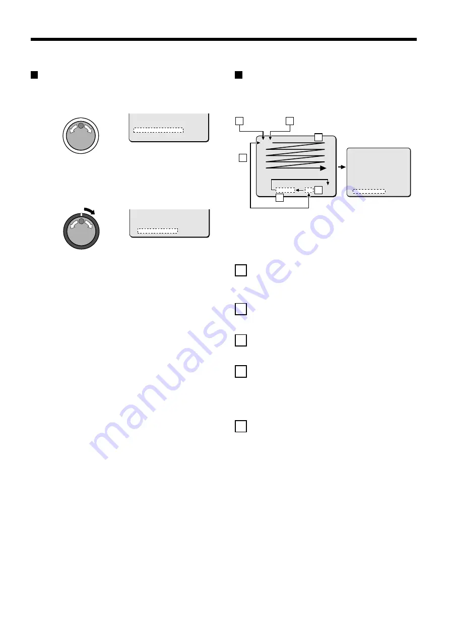
Use the jog dial to move the cursor to MOTION SENSOR, and then
turn the shuttle dial clockwise.

The motion sensor screen appears over the normal screen.

A

When the sensors are set to “OFF” (

-

) and the shuttle dial is

turned clockwise, the sensor is changed to “ON” (

ú

). The

setting switches between “ON” and “OFF” each time the
shuttle dial is turned clockwise.

B

When the jog dial is turned counterclockwise, the cursor
moves past “EXIT” and “LEVEL: OFF”, and then moves again
from the bottom to the top.

C

When the jog dial is turned clockwise and the cursor reaches
the bottom, it moves past “LEVEL: OFF” and “EXIT” and then
moves to the top.

D

The sensitivity can be adjusted when the sensor is set to “ON
(

ú

). Turn the jog dial to select “LEVEL: OFF”, turn the shuttle

dial clockwise, and then turn the jog dial to adjust the
sensitivity.

(OFF 1 – 10: The sensitivity increases as the number
becomes lower.)

E

If the cursor is at “EXIT” and the shuttle dial is turned
clockwise, the display returns to the ALARM REC MODE SET
screen.

 PRE-ALARM RECORDING   :  ON
   REC CYCLE : A0.24SEC.   DURATION:  5SEC
    => (14298 ALARMS CAN BE RECORDED)
 ALARM TRIGGER         :  ALARM
   MOTION SENSOR         ->
 

 PRE-ALARM RECORDING   :  ON
   REC CYCLE : A0.24SEC.   DURATION:  5SEC
    => (14298 ALARMS CAN BE RECORDED)
 ALARM TRIGGER         :  SENSOR
   MOTION SENSOR         ->
 

-

ú

-

-

-

-

-

-

-

-

-

-

-

-

-

-

-

-

-

-

-

-

-

-

-

-

-

-

-

-

-

-

-

-

-

-

-

-

-

-

-

-

-

-

-

-

-

-

-

-

-

-

-

-

-

-

-

-

-

-

-

-

-

-

-

-

-

-

-

-

-

-

-

-

-

-

-

-

-

-

          LEVEL : OFF        EXIT

( )

B

C

E

D

A

A

O F F   ( - )

O N   (

ú

)

           <ALARM REC MODE SET>
 PICTURE QUALITY       :  ENHANCED
 FRAME/FIELD RECORDING :  FIELD
 AUDIO RECORDING       :  OFF
 ALARM RECORDING       :  OFF
   REC CYCLE : 0.12 SEC.   DURATION:  5SEC
 PRE-ALARM RECORDING   :  ¤¤¤
   REC CYCLE : ¤¤¤  SEC.   DURATION:  ¤¤¤
   => (55682 ALARMS CAN BE RECORDED)
 ALARM TRIGGER         :  ALARM
   MOTION SENSOR         ->

English

55

Содержание DSR-3000P

Страница 1: ... des Gerätes sorgfältig durch Bewahren Sie die Anleitung zum späteren Nachschlagen auf À propos de ce manuel Avant d installer et d utiliser cet appareil veuillez lire ce manuel attentivement Assurez vous de le garder à portée de la main pour référence ultérieure Acerca de este manual Antes de instalar y usar este aparato lea detenidamente este manual Asegúrese de guardarlo a mano para futuras ref...

Страница 2: ...oid locations subject to strong vibrations Avoid moving the unit between cold and hot locations Do not place the unit directly on top of a monitor TV as this may cause playback or recording problems Avoiding Electrical Shock and Fire Do not handle the power cord with wet hands Do not pull on the power cord when disconnecting it from an AC wall outlet Grasp it by the plug If any liquid is spilled o...

Страница 3: ...NORMAL RECORDING AREA 18 SEARCHING FOR RECORDED IMAGES 23 SAVING COPYING RECORDED IMAGES 32 Copying images to the hard disk archive area 32 Copying images from archive area to a CompactFlash card 33 CompactFlash recording area 34 Copying to a DDS Digital Data Storage drive 35 MENU FLOW CHART AND MENU OPERATIONS 38 MENU flow 38 Basic menu screen operations 39 Operations while a sub menu screen is d...

Страница 4: ...ET setting 52 Pre alarm recording setting 54 Alarm trigger setting 55 Built in motion sensor settings 55 DISPLAY SET SETTING 57 DISPLAY SET setting 57 VIDEO LOSS SET setting 57 RS 232C RS 485 SET SETTING 58 RS 232C RS 485 SET setting 58 RS 232 Selection 58 RS 485 Selection 59 BUZZER SET SETTING 60 SECURITY LOCK SET SETTING 61 Operating privileges and security lock 61 A Administrator password setti...

Страница 5: ...ecorder in places with poor ventilation ACCESSORIES Power cord Ferrite core Fixer power cord tie Hard disk protection If any hard disk format errors are found when the power is turned on the whole hard disk is checked automatically If any further problems are found with the hard disk the POWER indicator flashes Please contact the place of purchase if you need to reformat the hard disk or make back...

Страница 6: ...wing order Displayed at top left Displayed at bottom left Displayed at top right Displayed at bottom right Off The indicator illuminates while information is displayed G SEARCH FRAME FIELD button and indicator During recording or when stopped When the button is pressed during recording or when the digital video recorder is stopped the indicator illuminates and search playback is possible During pl...

Страница 7: ...ed pair cable connection O Alarm connector Pin Signal C Ground ALARM IN Alarm input ALARM RESET Alarm reset input ALARM OUT Alarm output NON REC OUT Non rec output C Ground CLOCK ADJUST IN Clock sync input See page 41 CLOCK ADJUST OUT Clock sync output See page 41 WARNING OUT Hard disk error warning output FULL Hard disk space warning output ALARM OUT Alarm recording area space warning output P AC...

Страница 8: ...ALARM IN ALARM RESET NC C C OFF ALL RESET RS485 TERMINATE B A ON C RS485 REMOTE SUB OUT OUT DIGITAL VIDEO AUDIO S VIDEO SUB IN IN OUT OUT LOOP OUT LOOP OUT IN OUT IN MIC IN IN EJECT PC Card SLOT AUDIO IN Microphone input Video camera sold separately TV monitor sold separately VIDEO IN connector TV monitor sold separately S VIDEO IN connector Computer 32C SW OUT C C NC NC C C OFF ALL RESET RS485 TE...

Страница 9: ...arm input Alarm output DIGITAL IN DIGITAL OUT Ground C Cable straight type CAT 5 3 m or less AC IN RS232C ALA RM FU LL SW OUT W ARNIN G OUT FULL OUT IN ALARM OUT CLOCK ADJUST C C C NC C NON REC OUT ALARM IN ALARM RESET NC C C OFF ALL RESET RS485 TERMINATE B A ON C RS485 REMOTE SUB OUT OUT DIGITAL VIDEO AUDIO S VIDEO SUB IN IN OUT OUT LOOP OUT LOOP OUT IN OUT IN MIC IN IN EJECT PC Card SLOT AC IN R...

Страница 10: ...mportant images from the normal recording area and the alarm recording area The size of the archive area can be set to a maximum of 12 GB 15 of total capacity when using an 80 GB hard disk by changing the size of the normal recording area or the alarm recording area Archive area C Normal recording area Normal recording area Normal recording area A Alarm Alarm recording area Alarm recording area B ...

Страница 11: ... 0 13 8 5106H 3616H 2712H 1972H 1496H 0 10 10 6382H 4521H 3390H 2466H 1870H 0 05 20 12765H 9042H 6781H 4932H 3741H 0 03 40 25531H 18084H 13563H 9864H 7483H 0 02 60 38296H 27126H 20345H 14796H 11224H The tables below are recording speed tables provided for reference if the total capacity of the hard disk has been increased to 160 GB Contact the place of purchase for details on increasing the capaci...

Страница 12: ...the alarm display However the PRE display appears when pre alarm recording has been set When an alarm occurs the PRE is replaced by ALARM and the number of alarms also appears The alarm display shows the cumulative number of alarms If ALARM RECORDING is set ALARM appears ALARM flashes while an alarm is being recorded If PRE ALARM RECORDING is set PRE appears When playing images from the archive ar...

Страница 13: ... See page 47 Hard disk recording areas Normal recording area 80 Alarm recording area 19 Archive area 1 Picture quality EN Enhanced Recording method Field Recording speed 0 12 seconds 65H Note Playback is possible during recording When the PLAY STOP button is pressed during recording c appears in the operating display and images are played back from the point where recording began See page 19 Press...

Страница 14: ...EXIT OSD button Press the TIMER button The TIMER indicator illuminates and the digital video recorder switches to timer recording standby mode Note If SET in the TIMER SET menu is not set to ON or if the timer settings are not made correctly an alarm will sound when the TIMER button is pressed The TIMER indicator illuminates when the timer setting has been made correctly When the timer setting tim...

Страница 15: ... recording c appears in the operating display and images are played back from the point where recording began See page 19 Timer recording stops when the set end time is reached The TIMER indicator swithes off and the recording symbol a disappears from the operating display and recording stops Note Press the TIMER button to stop timer recording Timer recording then stops When the remaining area in ...

Страница 16: ...rts Alarm images are recorded in the alarm recording area Furthermore the number of alarms in the operating display is increased by one each time an alarm occurs Note Normal recording and timer recording stop when an alarm occurs during normal recording or timer recording Ending alarm recording Recording ends after the end of the alarm duration period default setting 1 sec The a and ALARM displays...

Страница 17: ...he operating display the ALARM indicator illuminates and pre alarm recording starts the a mark does not appear The same monitored image as in the normal recording area is recorded repeatedly in the alarm recording area Recording onto the hard disk proceeds automatically default setting according to the following settings The settings can be changed between long period recording and high quality re...

Страница 18: ...ing area in the alarm recording area reaches 1 the ALARM FULL indicator on the front panel flashes If recording is continued under these conditions the recording area is filled and the recording stops In the RECORDING AREA SET settings carry out the AREA FULL RESET operation for the normal recording area Recording will then be possible from the beginning again See page 44 ALARM 4 10 06 01 ALARM 00...

Страница 19: ...ssion ended Starting point for first playback Ending point Starting point for second playback Ending point Starting point for third playback Ending point PLAY STOP SEARCH ALARM FRAME FIELD STILL ZOOM SHUTTLE HOLD SHUTTLE HOLD b Skipping to the previous or next alarm See page 24 b Switching between frame and field See page 22 b Still image See page 21 b Zooming images See page 20 b Playback See pag...

Страница 20: ...ast forward playback starts If it is turned counterclockwise f appears in the operating display and rewind playback starts When you release the shuttle dial normal playback resumes PLAY STOP 1 26 10 01 11 02 50 EN 0 12SEC PLAY STOP 2 20 11 01 04 00 00 EN 0 12SEC 1 17 11 01 02 38 00 EN 0 12SEC 2 SHUTTLE HOLD Changing the playback speed Fast forward slow playback 1 Turn the jog dial clockwise Fast f...

Страница 21: ... Then turn the jog dial clockwise to move the zoom frame upward and turn it counterclockwise to move the zoom frame downward Move the zoom frame to the position to be enlarged Turn the shuttle dial The area inside the zoom frame is enlarged 2x Press the ZOOM button to cancel zooming The image zooming is canceled and normal playback continues Note The display cannot be enlarged even while monitorin...

Страница 22: ...ld Note If the jog dial is turned quickly the frame feed speed also increases STILL 1 17 11 01 02 38 00 EN 0 12SEC STILL 2 17 11 01 02 38 20 EN 0 12SEC 1 17 11 01 02 50 08 EN 0 12SEC During the following operations the picture may appear distorted or momentarily frozen This is normal and not a malfunction During the continuous playback from the normal and the alarm recording area the picture may b...

Страница 23: ...umbers channels can not be specified for playback When this operation is carried out only the specified channel is played back and so other channels are not displayed When a channel is selected the multiplexer title information and date information may not be fully displayed in some cases Switching between frame and field playback Press the SEARCH FRAME FIELD button while frame recording images ar...

Страница 24: ...H ALARM THUMBNAIL SEARCH TIME DATE SEARCH ARCHIVE AREA SEARCH MOTION DETECTION SEARCH MOVE JOG SELECT SHUTTLE ú ú ú ú ú ú ú ú ú LEVEL 6 EXIT MOTION DETECTION SEARCH SEARCH FROM NORMAL CHANNEL 4 START 28 10 01 08 00 END 28 10 01 20 00 MOTION SENSOR PREVIEW VIEW MOVE JOG SELECT SHUTTLE MOTION DETECTION SEARCH SEARCH FROM NORMAL CHANNEL 4 START 28 10 01 10 00 END 28 10 01 20 00 MOTION SENSOR PREVIEW ...

Страница 25: ...u can also use the shuttle dial or jog dial to carry out operations such as pausing and fast forward playback Alarm search starts playback from the image that was recorded at the instant the alarm occurred so if you are viewing pre alarm images use the shuttle operations to carry out rewind playback Alarm search 2 Press an ALARM skip button during playback If you press the û button playback skips ...

Страница 26: ...umbnails can be displayed When the jog dial is turned the previous or next alarm information screen appears To end this search mode press the SEARCH FRAME FIELD button Turn the shuttle dial clockwise The selected image appears in a single screen display and playback starts Note You can also use the shuttle dial or jog dial to carry out operations such as pausing and fast forward playback Only the ...

Страница 27: ...or as a single screen image Example To search for 8 pm on 26 October 2001 1 Turn the jog dial clockwise and then use the jog dial to change 25 to 26 2 Turn the shuttle dial clockwise and select 10 3 Turn the shuttle dial clockwise and select 01 4 Turn the shuttle dial clockwise and then use the jog dial to change 08 to 20 5 Turn the shuttle dial clockwise and select 00 Then turn the shuttle dial T...

Страница 28: ...and then turn the shuttle dial clockwise The preview image is displayed and played back in a single screen Note A single screen image can be displayed when date and time are entered and VIEW is selected even without displaying a preview You can also use the shuttle dial or jog dial to carry out operations such as pausing and fast forward playback 4 TIME DATE SEARCH RECORDING TOP 15 12 00 08 00 REC...

Страница 29: ...Turn the shuttle dial clockwise The selected image appears in a single screen display and playback starts Note A single screen image can be displayed when the cursor is moved to the image to be played back and the shuttle dial is turned clockwise even without displaying a preview You can also use the shuttle dial or jog dial to carry out operations such as pausing and fast forward playback SEARCH ...

Страница 30: ...huttle dial clockwise The ALARM display flashes Use the jog dial to select the recording area example NORMAL and then turn the shuttle dial clockwise The cursor moves to CHANNEL Note If the setting for MULTIPLEXER in the VIDEO INPUT SET menu is set to NO USE the cursor will move to START PREVIEW Examples of recording area selection ALARM Only images in the alarm recording area are searched NORMAL ...

Страница 31: ...e jog dial to set the END date and time example 8 00 pm on the current day for the motion sensor setting and then turn the shuttle dial clockwise The cursor moves to MOTION SENSOR Turn the shuttle dial clockwise The motion sensor setting screen appears Set the motion sensor to cover the area where you would like movement to be observed Move the cursor to EXIT and turn the shuttle dial clockwise Th...

Страница 32: ...hen turn the shuttle dial clockwise The display changes from the specified image to normal playback Note When using a multiplexer and the camera number has been specified as a channel when carrying out motion detector searches only images for the specified camera number will be played back For playback of all cameras the playback has first to be switched off and then switched on again Furthermore ...

Страница 33: ...the images in the normal recording area or alarm recording area that is to be copied and pause playback at the image that is to be copied See page 21 Example To copy 10 seconds of images starting from a selected image While the image to be copied is displayed as a still image press the COPY button The copy screen appears Use the jog dial to select COPY TO and then turn the shuttle dial clockwise T...

Страница 34: ...n while copying is in progress copying is canceled Copying images from archive area to a CompactFlash card 1 Insert a CompactFlash card into the CompactFlash slot on the front panel When inserting the CompactFlash card make sure that the direction of insertion is correct A microdrive can also be used for copying images Display an image from the archive area as a still image and then press the COPY...

Страница 35: ... MANY 10 PICTURES COPY TO COMPACT FLASH HOW MANY 10 SECONDES COPY TO COMPACT FLASH HOW MANY 10 SECONDES START CompactFlash recording area 1 A SANYO folder is created in the root directory 2 Sub folders for holding the copied images are created in sequence in the SANYO folder 3 The images are copied as JPEG files into the sub folders with filenames starting from 00000001 JPG HTML files called INDEX...

Страница 36: ...urn the shuttle dial clockwise ARCHIVING TO DDS DAT appears and copying then starts If you press the COPY button while copying is in progress copying is canceled When copying is completed ARCHIVE FINISHED appears Press any button to return to the normal screen Note When data is converted for storage on a DDS DAT drive the conversion process may result in an increase in the size of the data If copy...

Страница 37: ...o be read into the archive area and then turn the shuttle dial clockwise Reading of data starts The RESTORE FROM DDS DAT screen appears The image data on the DDS DAT drive is then saved into the archive area When all data has been read into the archive area RESTORE FINISHED appears When you play back the images in the archive area the image data that has been read can be played back COPY 1 ARCHIVE...

Страница 38: ...he shuttle dial clockwise The WARNING screen appears Use the jog dial to change NO to YES and then turn the shuttle dial clockwise ERASING MEDIUM appears and when erasing of data from the tape has been completed ERASING FINISHED appears COPY 1 ARCHIVE SET BACK UP RESTORE ERASE 2 WARNING STORED DATA ON DDS DAT WILL BE ERASED ARE YOU SURE NO CHANGE WITH JOG SET WITH SHUTTLE 3 01 01 01 08 00 00 EN 0 ...

Страница 39: ...G CONDITIONS SET DIGITAL SERIES RECORDING OFF TOTAL NUMBER RECORDING NUMBER NORMAL RECORDING AREA OVERWRITE ON ALARM RECORDING AREA OVERWRITE ON REMAINING DISK WARNING TIMER SET WEEK START STOP REC CYCLE SET SUN 0 12SEC 65H OFF MON 0 12SEC 65H OFF TUE 0 12SEC 65H OFF WED 0 12SEC 65H OFF THU 0 12SEC 65H OFF FRI 0 12SEC 65H OFF SAT 0 12SEC 65H OFF DLY 0 12SEC 65H OFF ALARM REC MODE SET PICTURE QUALI...

Страница 40: ...settings cannot be changed MENU MAIN MENU 1 1 LANGUAGE CLOCK SET 2 VIDEO INPUT SET 3 RECORDING AREA SET 4 RECORDING CONDITIONS SET 5 NORMAL REC MODE SET 6 TIMER SET 7 HOLIDAY SET 8 ALARM REC MODE SET TO MAIN MENU 2 MOVE LINES WITH JOG SELECT WITH SHUTTLE MAIN MENU 2 1 DISPLAY SET VIDEO LOSS SET 2 RS 232C RS 485 SET 3 BUZZER SET 4 SECURITY LOCK SET 5 NETWORK SET 6 HDD SET 7 POWER FAILURE USED TIME ...

Страница 41: ...oves to the 01 month setting and flashes 3 Use the same procedure to set the month 5 year 2002 hour 08 minutes 30 and seconds After the seconds have been set the cursor moves to the ADJUST TIME setting for EXT CLOCK SET and counting starts from zero seconds Note Time stops during clock setting LANGUAGE LANGUE SPRACHE IDIOMA ENGLISH CLOCK SET 01 01 2001 MON 00 00 00 SUMMER TIME SET MODE USE WEEK MO...

Страница 42: ...corder are also applied to these devices 1 Connect the other devices to the input terminal CLOCK ADJUST IN and output terminal CLOCK ADJUST OUT at the rear of the digital video recorder 2 Turn the jog dial to move the cursor to the ADJUST TIME setting and then turn the shuttle dial 01 flashes 3 Turn the jog dial to set the hours example 05 and then turn the shuttle dial 4 Press the EXIT OSD button...

Страница 43: ...ple and then turn the shuttle dial The cursor moves to MULTIPLEXER Note Select this if a Sanyo digital transport multiplexer MPX CD163P or CD93P has been connected digitally When making a multiplexer and a digital connection first connect the VIDEO OUT connector of this unit to the monitor and then set the input signal to DIGITAL 3 Press the EXIT OSD button The display returns to the normal screen...

Страница 44: ...WRITE setting is OFF before moving the cursor to AREA FULL RESET for either the NORMAL RECORDING AREA or the ALARM RECORDING AREA See page 45 When installing an additional hard disk and the MIRRORING of the HDD SET setting has been set to ON the TOTAL CAPACITY display of RECORDING AREA SET shows a smaller value for the hard disk capacity Resetting each recording area Example Set the normal recordi...

Страница 45: ...der will flash When writing to the hard disk is complete you can use playback operations to check the recordings 2 Use the jog dial to move the cursor to the AREA FULL RESET setting for the NORMAL RECORDING AREA and then turn the shuttle dial clockwise NO flashes on the WARNING screen 3 Use the jog dial to change NO to YES and then turn the shuttle dial clockwise The NORMAL RECORDING AREA is set t...

Страница 46: ... recorder which is used as the main unit should always have its connection number set to 1 Do not skip or overlap numbers when making the settings If NETWORK CONTROL in the NETWORK SET menu has been set to ON DIGITAL SERIES RECORDING cannot be selected Conversely if DIGITAL SERIES RECORDING has been set to ON NETWORK CONTROL cannot be set to ON Sub menus RECORDING CONDITIONS SET DIGITAL SERIES REC...

Страница 47: ...XIT OSD button The display returns to the normal screen When the remaining disk space in each area reaches 5 it is displayed in the operating display section The FULL for normal recording area or ALARM FULL for alarm recording area indicator on the front of the digital video recorder flashes Relationship between RECORDING AREA SET and OVERWRITE If the normal recording area and alarm recording area...

Страница 48: ...ckwise use the jog dial to set the recording speed example 0 16 and then turn the shuttle dial The cursor moves to PICTURE QUALITY Note The field and frame recording speeds vary depending on the PICTURE QUALITY setting Refer to the Recording speed table for details See page 10 7 Press the EXIT OSD button The display returns to the normal screen NORMAL REC MODE SET PICTURE QUALITY ENHANCED FRAME FI...

Страница 49: ...icture quality frame field recording and audio recording settings for timer recording will be the settings used for recording in the normal recording area Timer reservations every day at the same time with the same image quality Example Timer recording every day from 8 30 a m to 6 30 p m at the same recording speed 1 Press the MENU button to select TIMER SET and then turn the shuttle dial clockwis...

Страница 50: ...be SUPER FINE Then recording speed the same as the speed previously set 9 Use the jog dial to change OFF to ON and then turn the shuttle dial clockwise The cursor moves to MON 10 Press the EXIT OSD button The display returns to the normal screen Note If you want to use different days times and recording speeds for timer recording select the respective WEEK column and make the required settings If ...

Страница 51: ...not need to be set appear with a symbol 6 Use the jog dial to change from TUE to WED and then turn the shuttle dial clockwise hours flashes in the STOP column 7 Use the jog dial to change from to 20 and then turn the shuttle dial clockwise minutes flashes in the STOP column 8 Use the jog dial to change from to 30 and then turn the shuttle dial clockwise 0 12 recording speed flashes in the REC CYCL...

Страница 52: ...1 3 Use the jog dial to change from to 17 and then turn the shuttle dial clockwise month flashes in the line 1 4 Use the jog dial to change from to 11 and then turn the shuttle dial clockwise The cursor moves to the line 2 5 Follow the same procedure to set other holiday dates 6 Press the EXIT OSD button The display returns to the normal screen HOLIDAY SET 1 11 2 12 3 13 4 14 5 15 6 16 7 17 8 18 9...

Страница 53: ...ORDED ALARM TRIGGER ALARM MOTION SENSOR Sub menus Main menu 1 Sets the image quality Sets the recording method frame or field Sets audio recording Sets alarm recording Sets the recording rate recording speed and the alarm time duration Sets pre alarm recording Sets the recording rate recording speed and the alarm time duration for pre alarm recording Sets the alarm trigger Sets the motion sensors ...

Страница 54: ...r This cannot be used for normal recording Note If alarm recording is set to a setting such as MODE1 PRE ALARM RECORDING setting will be enabled will change to OFF 7 Turn the shuttle dial clockwise use the jog dial to set the recording speed example 0 16 and then turn the shuttle dial DURATION of 1SEC flashes Note When the recording speed is selected the maximum number of recordings appears after ...

Страница 55: ...re alarm recording images If using the digital video recorder together with a multiplexer the switching signal from the multiplexer will be output in accordance with the digital video recorder s recording timing for normal recording if pre alarm recording and normal recording are being carried out at the same time Because of this if the recording cycle for pre alarm recording is shorter than the r...

Страница 56: ...settings The monitor screen 8x10 can be displayed on the monitor screen so that detection of suspicious people alarms can be carried out more easily The default setting is for all motion sensors to be OFF so that they cannot detect the movement of objects Motion sensor screen Use the jog dial to move the cursor to MOTION SENSOR and then turn the shuttle dial clockwise The motion sensor screen appe...

Страница 57: ...e 6 Display examples Sensitivity settings OFF Sensor does not operate 1 to 10 Sensor operates the lower the value the greater the sensitivity 4 Turn the shuttle dial clockwise twice This completes the motion sensor settings and the display is returned to the ALARM REC MODE SET screen 5 Press the EXIT OSD button The display returns to the normal screen Note Change the ALARM setting for the ALARM se...

Страница 58: ...LARM RECORDING in the ALARM REC MODE SET menu has been set to OFF ALARM COUNT and ALARM TYPE do not appear When set to ON ALARM appears in the operating display during alarm recording PRE appears in the operating display during pre alarm recording ARCHIVE appears when playing back images in the archive area 7 Press the EXIT OSD button The display returns to the normal screen VIDEO LOSS SET setting...

Страница 59: ...l clockwise This completes the setting and the cursor moves to CONTROL Communication speeds 2400 4800 9600 and 19200 3 Press the EXIT OSD button The display returns to the normal screen RS 232C RS 485 SET CONTROL RS 232C DATA SPEED 19200 STATUS INFO ALARM INFO ADDRESS Main menu 2 Sub menus Selects CONTROL Sets communication environment Setting for RS 485 only Enables transmission of status Enable ...

Страница 60: ...o ALARM INFO 4 Turn the shuttle dial clockwise use the jog dial to select alarm information example ON and then turn the shuttle dial clockwise ON Alarm information will be transmitted The cursor moves to ADDRESS 5 Turn the shuttle dial clockwise use the jog dial to select an address example 37 and then turn the shuttle dial clockwise This completes the setting and the cursor moves to CONTROL Note...

Страница 61: ...te When an item is set to ON the buzzer sounds twice at an interval of about 0 5 seconds KEY IN ON Sets the buzzer to sound each time an operating button is pressed NON REC ON Sets the buzzer to sound when recording stops by itself and when another person deliberately stops recording 5 Press the EXIT OSD button The display returns to the normal screen BUZZER SET ALARM OFF DISK FULL ON DISK ERROR O...

Страница 62: ...sword cannot be set The password can consist of between four and eight alphanumeric characters 3 Turn the shuttle dial clockwise The first password entry bar flashes 4 Use the jog dial to display 1 and then turn the shuttle dial The second password entry bar flashes The characters that can be used in the password are 0 1 9 A B C Z 5 Use the jog dial to display 2 and then turn the shuttle dial The ...

Страница 63: ...he jog dial to display A and then turn the shuttle dial The second password entry bar flashes The characters that can be used in the password are 0 1 9 A B C Z 3 Use the jog dial to display B and then turn the shuttle dial The third password entry bar flashes 4 Repeat this procedure to continue entering 123456 and then turn the shuttle dial clockwise The cursor moves to OFF and flashes 5 Use the j...

Страница 64: ...ng 3 Press the EXIT OSD button The display returns to the normal screen D Security lock setting 1 At the normal monitoring screen press and hold the SUHTTLE HOLD button for approximately 3 seconds The LOCK indicator at the front panel illuminates and the buzzer sounds The security lock is then set 2 Press any operating button to check the security lock The password entry screen appears The screen ...

Страница 65: ... DE 660 Note Correct operation cannot be guaranteed if a LAN card other than the one recommended above is used 5 Use the jog dial to select the LAN card example LAN1 and then turn the shuttle dial clockwise The cursor moves to NETWORK CONTROL NETWORK SET LAN CARD LAN1 NETWORK CONTROL OFF IP ADDRESS 192 168 0 1 SUBNET MASK 255 255 255 0 GATEWAY 0 0 0 0 PASSWORD SETTING ID PASSWORD 4 8 ID1 1111 ID2 ...

Страница 66: ...T MASK and GATEWAY settings with the LAN Network Administrator PASSWORD SETTING setting For network connection there are three access levels each of which has a password Each password can consist of a combination of 4 to 8 alphanumeric symbols Note The cursor cannot be moved to ID or PASSWORD 4 8 Example Set AB123456 as the ID1 password 1 Use the jog dial to move the cursor to ID1 and then turn th...

Страница 67: ...he cursor moves to ID2 5 As required use the same procedure to set passwords for ID2 and ID3 and then turn the shuttle dial clockwise The cursor moves to LAN CARD 6 Press the EXIT OSD button The display returns to the normal screen PASSWORD SETTING ID PASSWORD 4 8 ID1 AB123456 ID2 2222 ID3 3333 EXIT OSD 66 English ...

Страница 68: ...SET screen MIRRORING When a hard disk is added it is possible to record the same image on two hard disks This means that even if an image write error occurs you will be able to read from an area where there is no write error Note that if mirroring is specified the upper limit of recording speed will be limited PLAYBACK DRIVE After MIRRORING has been set you will be able to specify which of the two...

Страница 69: ...the left example 020 When the number exceeds 999 it returns to 000 2 RECOVER Shows the date time when power was restored 3 DISK1 USE Shows the total hard disk 1 usage time 4 DISK2 USE Shows the total hard disk 2 usage time 5 POWER Shows the total usage time for this unit POWER FAILURE USED TIME POWER FAILURE 020 FAILURE RECOVER USED TIME DISK1 USE 00000H DISK2 USE H POWER 00000H MAIN MENU 2 1 DISP...

Страница 70: ...for a response from the digital video recorder and then transmits the next byte of data To start sending commands an ON F6 command is sent The digital video recorder will continue to receive commands until an OFF F7 command is sent to stop The digital video recorder sends an ACK OA each time it receives a command See Table 4 Command Table on page 71 RS 485 Data format Mode Asynchronous Character l...

Страница 71: ...ll devices in between devices other than the first and last in the series to OFF Note If the termination settings are not correct data will be reflected by either end of the series and this will affect the transmission of other data so that the data that is transmitted to each device will not be correct Example System controller Multiplexer Digital video recorder Termination switch Time lapse VCR ...

Страница 72: ... TIMER ON OFF 1 2 3 SHIFT SHIFT 4 SHIFT SHIFT MENU 5 SHIFT RP UP 6 SHIFT RP DOWN 7 8 9 SECURITY LOCK ON A ACK PLAY REV PLAY SEARCH DVR B NAK C GROUP SET D GROUP CHECK E GROUP CLEAR F STOP STILL Upper bit 8 9 A B C D E F Lower bit 0 CLOCK ADJUST 1 MENU RESET 2 3 4 5 ZOOM MPX 6 7 STATUS SENSE 8 MENU UPLOAD MENU DOWNLOAD 9 CLOCK DOWNLOAD A REC REC DUB REQUEST B FF ALARM F C CHANNEL REW ALARM R D COPY...

Страница 73: ...75 Ω unbalanced synchronous C signal 0 300 Vp p 75 Ω unbalanced Loop out terminal 1 0 Vp p 75 Ω unbalanced BNC x 1 S video loop out terminal Separate YC signals DIN connector S terminal x 1 Y signal 1 0 Vp p 75 Ω unbalanced synchronous C signal 0 300 Vp p 75 Ω unbalanced Digital output terminal RJ 45 x 1 Digital SUB output terminal RJ 45 x 1 Audio output terminal 8dBs 600 Ω unbalanced RCA pin jack...

Страница 74: ...SANYO Electric Co Ltd 1AC6P1P2473 A L8HAA XE 0202KP CZ Printed in Japan L8HAA XE DSR 3000 GB 2002 2 4 ...

Отзывы: