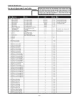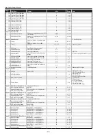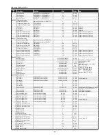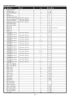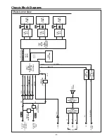
-6-
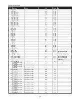
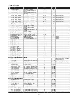
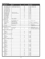
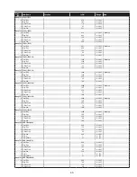
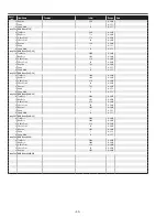
Electrical Adjustments
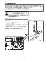
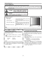
1. Receive the 16-step grey scale 480i-component signal
with
computer1 [component]
mode.
. Enter the service mode.
3. Connect an oscilloscope to test point “
tPG1
” (+) and
chassis ground (-).
4. Select group no. “
0
”, item no. “
0
” and change data val-
ue to adjust the pedestal level and black level to be the
same level.
5. Connect an oscilloscope to test point “
tPr1
” (+) and
chassis ground (-).
6. Select item no. “
1
” and change data value to adjust the
pedestal level and black level to be the same level.
7. Connect an oscilloscope to test point “
tPB1
” (+) and
chassis ground (-).
8. Select item no. “
2
” and change data value to adjust the
pedestal level and black level to be the same level.
P
edestal Lebel
Blac
k Lebel
c
Pedestal adjustment [480i]
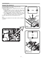
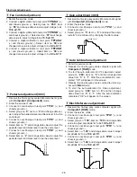
1. Receive the 16-step grey scale 480i-component signal
with
computer1 [component]
mode.
. Enter the service mode.
3. Connect an oscilloscope to test point “
tPG1
” (+) and
chassis ground (-).
4. Select group no. “
0
”, item no. “
3
” and adjust the ampli-
tude “
a
” to be minimum by changing the Data value.
(a)
White Level
v
Gain adjustment [480i]
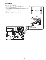
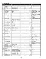
1. Receive the 16-step grey scale computer signal with
computer1 [rGB]
mode.
. Enter the service mode.
3. Connect an oscilloscope to test point “
tPG1
” (+) and
chassis ground (-).
4. Select group no. “
100
”, item no. “
124
” and change data
value to adjust amplitude “
a
” to be
10.0 ±0.1V
.
5. Connect an oscilloscope to test point “
tPr1
” (+) and
chassis ground (-).
6. Select item no. “
125
” and change data value to adjust
amplitude “
a
” to be
10.0 ±0.1V
.
7. Connect an oscilloscope to test point “
tPB1
” (+) and
chassis ground (-).
8. Select item no. “
126
” and change data value to adjust
amplitude “
a
” to be
10.0 ±0.1V
.
(a)
black level
black level
n
Black Reference adjustment
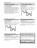
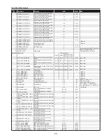
1. Enter the service mode.
. Receive the 16-step grey scale computer signal with
computer1 [rGB]
mode.
3. To start the auto-calibration for PC adjustment, select
group no. “
260
”, item no. “
0
” and then change data
value from “
0
” to “
1
”. After the auto-calbration com-
pleted, "OK" will appear on the screen.
4. Receive the 16-step grey scale composite video sig-
nal with
Video
mode.
5. To start the auto-calibration for Video adjustment,
select group no. “
260
”, item no. “
0
” and then change
data value from “
0
” to “
1
”. After the auto-calbration
completed, "OK" will appear on the screen.
b
Auto Calibration adjustment
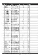
1. Eenter the service mode.
. Connect a digital voltmeter to test point “
tPFANA
” (+)
and chassis ground (-). Select group no. “
250
”, item
no. “
95
” and change data value to adjust voltage to be
13.5 ±0.1V
.
3. Connect a digital voltmeter to test point “
tPFANB
” (+)
and chassis ground (-). Select item no. “
97
” and change
data value to adjust voltage to be
13.5 ±0.1V
.
4. Connect a digital voltmeter to test point “
tPFANA
”
(+) and chassis ground (-). Select item no. “
94
” and
change data value to adjust voltage to be
5.0 ±0.1V
.
5. Connect a digital voltmeter to test point “
tPFANB
”
(+) and chassis ground (-). Select item no. “
96
” and
change data value to adjust voltage to be
5.0 ±0.1V
.
x
Fan Control adjustment
Содержание 1 122 356 20
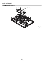
Страница 18: ... 18 Optical Parts Disassembly m Optical Unit Top removal M3x8 x5 Optical top Fig 7 ...
Страница 53: ... 53 IC Block Diagrams FA5502 P F Control IC621 L3E6100D D A S H LCD Driver IC501 IC531 IC561 ...
Страница 54: ... 54 IC Block Diagrams L3E07072 LCD Driver Gamma Correction IC401 M62393 DAC IC3531 ...
Страница 55: ... 55 IC Block Diagrams NJW1141 Audio Control IC5001 ...
Страница 74: ...Key No Part No Description Key No Part No Description KR6 XW55A00 KP6 XW50A00 Electrical Parts List 74 ...
Страница 81: ...KR6 XW55A00 KP6 XW50A00 81 Mechanical Parts List ...
Страница 82: ... KR6AD Jun 2007 DC 350 Printed in Japan SANYO Electric Co Ltd ...
Страница 92: ...A8 SCH_KR6AD 1 3 4 5 6 7 8 9 10 11 1 13 14 15 16 A B C D E F G H I J K L A B C D E F G H I J K L NO DATA ...


