Santec LCOS-SLM Скачать руководство пользователя страница 1

1

Operational Manual

LCOS-SLM

Liquid Crystal Based Spatial Light Modulator

SLM-200

OPERATIONAL MANUAL

Doc.#: SS-18-0442-04

Date: 26, Sep. 2018

Ver.4.0

Содержание LCOS-SLM

Страница 1: ...1 Operational Manual LCOS SLM Liquid Crystal Based Spatial Light Modulator SLM 200 OPERATIONAL MANUAL Doc SS 18 0442 04 Date 26 Sep 2018 Ver 4 0...

Страница 2: ...the event of any mistake please contact us Notes in Bringing This Product Out of Japan 1 When this product is brought out of Japan some laws or regulations of a destination country may prohibit this p...

Страница 3: ...tions 2 1 Parameters 2 2 Operating principles 2 3 Part names and functions 2 4 LED status notifications 2 5 Trigger signal specifications 3 SLM handling instructions 3 1 Connections 3 2 Power up seque...

Страница 4: ...e gamma control The signal is addressed via a standard DVI Digital Visual Interface signal e g by a PC s graphics The SLMs are characterized by ultra low phase fluctuation from high drive frequency ov...

Страница 5: ...Do not place in an area subject to noise by electric field magnetic field etc Do not place in an area where the unit is subject to falling objects Do not place in an area with possible exposure to wa...

Страница 6: ...6 Introduction Figure 2 LCOS unit handling...

Страница 7: ...6 USB3 0 TypeA B cable 7 SMB BNC cable 8 Polarizer Wavelength 450 700 nm 9 CD ROM Control software GUI User operational manual Separate model 1 LCOS SLM body 2 LCOS unit 3 Bracket for LCOS unit 4 AC...

Страница 8: ...8 Introduction 1 5 Warranty The warranty of the product is based on santec document Doc SA 15 0308...

Страница 9: ...90 levels at 25degC typ 3 The value is not guaranteed Electrical and Mechanical characteristics Min Max Units Notes Hz 100 240 VAC mm All in one model kg Separate model kg Width x Depth x Height 117 6...

Страница 10: ...play specifications Six types of AR coating are available as shown in Figure 4 5 1 450 550nm 2 750 850nm 3 1000 1100nm 4 1500 1650nm 5 400 700nm 6 450 550 1500 1650nm Figure 4 AR reflectivity angle 0...

Страница 11: ...Figure 5 AR reflectivity angle 30 degree 11 Display specifications Reference data Reference data...

Страница 12: ...12 Display specifications Figure 6 Dimensions All in one model Unit mm...

Страница 13: ...13 Display specifications Figure 7 Dimensions Separate model Unit mm...

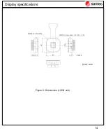
Страница 14: ...14 Display specifications Figure 8 Dimensions LCOS unit Unit mm...

Страница 15: ...s pixel by pixel Optical phase or intensity can be controlled spatially by the voltage level applied to each pixel The SLM can be controlled via a PC using the DVI and USB interface Easy control using...

Страница 16: ...ber legs x4 Label Model name and S N Side view1 Control panel Side view2 M6 screw for mounting Side view3 1 4 inch screw for mounting display LCOS panel M6 screw for mounting inch screw for mounting L...

Страница 17: ...14 Side view 2 M6 screw for mounting Display specifications DVI interface DC socket Reset button Power status LED Clock status LED Signal status LED Clock status LED M6 screw for mounting Trigger Inp...

Страница 18: ...15 Side view 3 1 4 inch screw for mounting Display specifications 1 4 inch screw for mounting Figure 16 Side view 4 M2 6 screw M2 6 Screw M6 and 1 4 inch mounting blocks can be fixed to user preferab...

Страница 19: ...18 Back view Display specifications Flex cable for connecting LCOS unit Label Model name and S N Connector for connecting LCOS unit Side view2 M6 screw for mounting Side view3 1 4 inch screw for moun...

Страница 20: ...1 Control panel Figure 20 Side view 2 M6 screw for mounting DVI interface DC socket Reset button Power status LED Clock status LED Signal status LED Clock status LED M6 screw for mounting Trigger inp...

Страница 21: ...21 Figure 21 Side view 3 1 4 inch screw for mounting Display specifications 1 4 inch screw for mounting M6 and 1 4 inch mounting blocks can be fixed to user preferable sides...

Страница 22: ...22 Front view Display specifications Figure 23 Back view Heat sink LCOS panel Electrode pads for connecting SLM body LC director Note Input linear polarized light shall be parallel to the LC director...

Страница 23: ...23 Figure 24 Side view Display specifications 6 M2 6 screw hole for mounting...

Страница 24: ...24 Display specifications Polarization axis Note Please check the SLM surface visually through attached polarizer Figure 25 Polarizer setting No pattern Stripe pattern Polarizer LC director...

Страница 25: ...ns Label Color Normal Switching status Power Green LED ON LED OFF when the power supply voltage is less than 4 5V 5V 10 LED1 Green LED ON LED OFF when clock signal condition of LCOS display driver is...

Страница 26: ...gs Symbol MIN MAX UNIT VI 0 5 V Electrical Characteristics Symbol MIN MAX UNIT High level input voltage VIHTH 3 5 V Low level input voltage VILTH 1 5 V Trigger output Electrical Characteristics MIN MA...

Страница 27: ...imum Output trigger signal Pattern_B Pattern_B Input trigger signal LCOS display Pattern_A Pattern_A Pattern_A Pattern_B Input trigger signal LCOS display Output trigger signal Pattern_A Pattern_A 40...

Страница 28: ...27 Please make sure you connect the device to the computer before connecting it to the power supply SLM handling instructions Figure 26 SLM power connections All in one model AC adapter DVI HDMI cabl...

Страница 29: ...re 27 SLM power connections Separate model LCOS unit Refer to the next page how to connect LCOS unit AC adapter DVI HDMI cable Do not use attached AC cable in other products AC adapter DC 5V AC100 240...

Страница 30: ...gure 28 Connection method of LCOS unit Separate model Step A Turn the arrow seal face on FPC upward And raise the lock bar up Step B Insert the FPC connector into the end Step C Turn the lock bar down...

Страница 31: ...nd start voltage supply There is no power switch on the SLM body SLM is powered on by the voltage supply 3 The LCOS DVI interface is displayed on the PC screen You can check the pattern directly on th...

Страница 32: ...e screw bar as shown in figure 30 3 3 2 Separate model The LCOS unit has two screw holes M4 and 8 for mounting to experimental stages For example the LCOS unit can be mounted to a slide stage using a...

Страница 33: ...and using lint free optical wipes air blower or a liquid solvent such as isopropyl alcohol Do not use acetone SLM handling instructions Figure 28 Cleaning the LCOS display window by lint free cotton s...

Страница 34: ...PC specifications for this software are as follows OS Windows7 32bit Display resolutions 1920x1200 Video output HDMI Interface USB2 0 3 0 SLM version SLM 200 SLM 250 SLM 100 and 150 is not supported...

Страница 35: ...1 USB driver installation procedure 1 SLM Power ON after connecting control PC and SLM via USB interface Please install the device driver in attached CD when you see following error message Software p...

Страница 36: ...36 2 Please select Browse my computer for driver software Software package...

Страница 37: ...37 3 Select adequate OS folder on attached CD contents Software package...

Страница 38: ...38 4 Installation of USB driver Software package...

Страница 39: ...OS display software installation procedure 1 Install the control software by starting the setup exe Please select adequate language for installation Attached CD E SLM 200 GUI Installer setup exe Softw...

Страница 40: ...40 2 Specify the folder to install software Default C Program Files santec SLM 200 GUI Click next 3 Specify and confirm a folder for the program shortcuts Software package...

Страница 41: ...41 4 If you create the file shortcut on desktop click the checkbox and click next 5 Click install and start installation Software package...

Страница 42: ...42 6 If you launch the GUI after installation click the checkbox and click Finish Software package...

Страница 43: ...43 4 2 Software operation 4 2 1 GUI window 1 Menu tab 2 Shortcut menu 3 Preview of LCOS displayed phase pattern Software package 1 2 3...

Страница 44: ...44 4 2 2 Menu tab 4 2 2 1 Open CSV file The CSV file with data format described in figure 30 can be opened The data can be edited using spreadsheet like Microsoft excel Software package...

Страница 45: ...eadsheet like Microsoft excel Software package Figure 30 Data format of pattern files a All in one model b Separate model LCOS unit Y Vertical pixel number Usable key Gray scale level for each pixel 0...

Страница 46: ...46 4 2 2 2 Recent file The GUI memorizes the 4 past files They can be displayed on the LCOS panel 4 2 2 3 Save Save as Current preview on GUI can be saved or saved as a new file Software package...

Страница 47: ...24 bit format Select the BMP file for converting If the BMP file is converted in rescaling of screen resolution magnification and grey scale of blank area can be specified Maximum screen resolution o...

Страница 48: ...COS Format R7 R6 R5 G7 G6 G5 B7 B6 B5 B4 10bit phase steps 0 1024 Red Green Blue 0 0 0 0 1 0 0 16 2 0 0 32 3 0 0 48 4 0 0 64 126 0 224 224 127 0 224 240 128 32 0 0 129 32 0 0 130 32 0 0 510 96 224 224...

Страница 49: ...2 2 5 Display center point The cross mark indicating display center can be selected whether it is displayed or not 4 2 2 6 Center point color The color of cross mark can be changed 49 Software packag...

Страница 50: ...4 2 2 7 Change preview The gray level for preview of 8bit or 10bit can be selected 50 Software package 10bit preview 8bit preview...

Страница 51: ...51 4 2 2 8 Set CSV pattern The preview of specified display data is displayed Software package...

Страница 52: ...played image files are selected and moved to Selected files box as shown in the figure below Maximum number of selected files at a time is 128 CSV files stored in reference folder described in followi...

Страница 53: ...files continuously with specified regular interval and loop count Available range for interval and loop count DVI mode 0 1 sec Interval 10 0 Loop count 500 0 Memory mode Pattern capture mode 0 sec Int...

Страница 54: ...mode displays the image files in input trigger timing and continue until clicking Exit button 4 2 2 9 4 Change the order of registered files The order of displayed image files can be changed from the...

Страница 55: ...dance with the same procedure as 4 2 2 11 displayed image files are selected After registering the image files the following dialog box is displayed The image file selected by double click or pushing...

Страница 56: ...image displayed on the LCOS panel can be changed By specifying the pixel number for translation on the X and Y axes the position of the displayed image can be shifted Available translation range 1920...

Страница 57: ...y scale of all pixels for the displayed image can be offset at a specified level By specifying the offset level of the gray scale on the dialog box below the offset image is displayed Available offset...

Страница 58: ...gray scale of all pixels for the displayed image can be rescaled with a specified value By specifying the gain value for rescaling on dialog box below the displayed image can be rescaled Available gai...

Страница 59: ...to 1600nm can be set at a 1 nm interval If No wavelength calibration is selected the phase level is adjusted for 1550nm Maximum optical phase at specified wavelength can be adjusted to the inputted va...

Страница 60: ...60 4 2 2 15 Launch CGH generator The CGH Computer Generated Hologram phase pattern can be generated from specified image file Software package...

Страница 61: ...6 Full screen contrast The entire LCOS display can be controlled to specified 10bit contrast level from 0 to 1023 The contrast level can change slider control or entering specified value 61 Software p...

Страница 62: ...can be captured and stored in memory The displayed pattern on LCOS in the timing of clicking Capture button is captured Captured pattern is numbered according to specified number in Pattern No and can...

Страница 63: ...63 Captured patterns can be displayed in Set continuous mode or selecting display files directly Software package...

Страница 64: ...4 2 2 18 Set trigger output The output trigger can be set ON or OFF ON Trigger signal output in timing of display change OFF No trigger output 64 Software package...

Страница 65: ...nput patterns via DVI D DVI Memory mode Displayed memory patterns stored in SLM via USB Max 128 patterns Pattern capture mode Captured patterns displayed on LCOS via DVI D and stored in SLM internal m...

Страница 66: ...P file to CSV file Display center point Center point color Change preview Set CSV pattern Set continuous mode Selection directory files Translate all screen Offset gray scale of all screen Gain adjust...

Страница 67: ...ark 4 2 2 21 Zoom out Preview display is reduced at the center of cross mark 4 2 2 22 Fit full size Preview is displayed full screen 4 2 2 23 Marquee zoom Selected area is expanded on preview display...

Страница 68: ...4 3 CGH generator 4 3 1 GUI window 1 Menu tab 2 Shortcut menu 3 CGH parameters 4 Original image 5 CGH image 6 Computed reconstruction image 68 Software package 1 2 3 4 5 6...

Страница 69: ...69 4 3 2 BMP file format for CGH generation Prepare BMP file for CGH generation Effective image size is 1024 1024 pixel 8 bit grayscale Software package...

Страница 70: ...70 4 3 3 Effective area of BMP image Software package...

Страница 71: ...4 3 4 CGH generation 1 Open BMP file for target image 71 Software package Make sure to confirm your original image on the window...

Страница 72: ...le Calculation time strongly depends on the loop number The setting 20 is recommended for an adequate accuracy 2 3 Select files type for saving Image2 bmp Saved calculated CGH pattern as BMP file type...

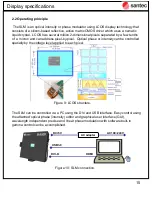
Страница 73: ...3 Start calculation 73 Software package The created CGH image and the display image appear after file saving...

Страница 74: ...U S A SANTEC U S A CORPORATION Toll Free 1 201 488 5505 Fax 1 201 488 7702 Grand Union Studios 332 Ladbroke Grove London W10 5AD SANTEC EUROPE LIMITED Tel 44 20 3176 1550 11F Room E Hua Du Bldg No 838...

Отзывы: