background image

C o n t e n t s

C h a p t e r   1   B r i e f   i n t r o d u c t i o n ......................................................................1

1.1 Product introduction........................................................................................................1
1.2 Frequently used symbols.................................................................................................2

C h a p t e r   2   E x t e r i o r   a p p e a r a n c e

.......................................................................3

2.1 Unpacking inspection......................................................................................................3
2.2 Exterior gure..................................................................................................................5
2.3 Panel instructions............................................................................................................6

C h a p t e r   3   I n s t a l l a t i o n   i n s t r u c t i o n s

...............................................................8

3.1 Installation Notice...........................................................................................................8
3.2 Installation space.............................................................................................................8
3.3 Installation and wiring connection diagram...................................................................10
3.4 Requirements of wiring cables and protect device for Castle EX series UPS.....................14

3.5 Parallel UPS installation................................................................................................15
3.6 Procedures of connecting battery bank to UPS.............................................................18

C h a p t e r   4   O p e r a t i o n

.............................................................................................19

4.1 Single UPS operation.....................................................................................................19

4.2 Parallel UPS operation................................................................................................... 26

C h a p t e r   5   C o m m u n i c a t i o n   I n t e r f a c e

..........................................................28

C h a p t e r   6   O p t i o n a l   a c c e s s o r i e s

.........................................................32

6.1 Power Feedback Module...............................................................................................32
6.2 Transformer...................................................................................................................32
6.3 Double Charge Boards...................................................................................................33

6.4 Temperature Sensor.......................................................................................................33

6.5 Dustproof Net...............................................................................................................33
6.6 IP21 Option...................................................................................................................34

C h a p t e r   7  Tr a n s p o r t a t i o n ,   M a i n t e n a n c e   a n d  Tr o u b l e s h o o t i n g................35

A p p e n d i x   1 Te c h i n i a l   p a r a m e t e r s   a n d   s p e c i f i c a t i o n s ............................37

A p p e n d i x   2   L i g h t   r e f e r e n c e   t a b l e ..........................................................38

A p p e n d i x   3     Wa r r a n t y...................................................................................40

Содержание 3C3 EX 20KS

Страница 1: ...www electway net...

Страница 2: ...kept properly for future reference Do not attempt to operate the UPS until reading through all safety information and operating instructions of this manual carefully This manual applies to the Castle...

Страница 3: ...nd input the supervision code Tel inquiry Call 95001111 to check you may call 010 95001111 and follow the instructions to enquire the identi cation Message inquiry Send text message to 106695001111 av...

Страница 4: ...extinguisher should be used properly Using liquid re extinguisher may result in electric shock hazard 8 Storey bearing capacity of machine and batteries should be taken into consideration prior to in...

Страница 5: ...nly personnel with proper expertise can carry out the maintenance of accumulator batteries Replacement of accumulator batteries requires a match of same type and model with equal quantity 3 As accumul...

Страница 6: ...of the UPS 4 For long term inaction the battery should be charged once every three moths in normal temperature environment and once every two moths in high temperature environment with no less than 10...

Страница 7: ...Castle EX series UPS 14 3 5 Parallel UPS installation 15 3 6 Procedures of connecting battery bank to UPS 18 Chap ter 4 Op er at i on 19 4 1 Single UPS operation 19 4 2 Parallel UPS operation 26 Chap...

Страница 8: ...astle EX Series Manifold function of Castle EX series products to provide high quality power supply guarantee for your device Advanced DSP digital control technology to effectively improve product per...

Страница 9: ...used symbols The following symbols will be frequently used in this User Manual as well as in the process of actual application therefore correct identi cation and understanding of their connotations...

Страница 10: ...s damaged during the process of transportation or not Should any damage be observed or parts be found missing do not start the machine Contact the forwarder and distributor immediately 1 Remove the to...

Страница 11: ...3C3 EX 60KS 80KS models remove the iron brackets xing the UPS with a wrench rstly then move the frame smoothly from the pallet to the ground and x the UPS with the iron brackets again Note 1 3C3 EX 20...

Страница 12: ...2 2 Exterior gure Exterior gure of 3C3 EX 20KS 30KS 40KS UPS Front view Front view without front panel 5 Rear view 3C3 EX 20K Rear view 3C3 EX 30KS 40KS...

Страница 13: ...arry out the visual operations of the UPS including the power on power off status display fault alarm parameter setting etc And all the operations of the UPS can be realized through the LCD panel afte...

Страница 14: ...S information Function Keys selecting and opening menu items accessing information and changing system parameters etc Identi er Key Name Function Con rm Enter Select a menu or con rm an operation con...

Страница 15: ...t temperature for normal UPS performance should not exceed 50 4 It is suggested that battery pack should work within a temperature range from15 to 25 5 Altitude for normal UPS function should not exce...

Страница 16: ...o less than 500mm otherwise the UPS internal temperature will rise dramatically Do not install the UPS under the outtake of an air conditioner otherwise the water may drop into the UPS and thus cause...

Страница 17: ...vice engineers according to customer s request All the operations should only be carried out by the technical personnel of the company or authorized by the company Do not open the case cover arbitrari...

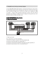
Страница 18: ...diagram For dual power input the conducting wire between AC input terminal and bypass input terminal must be removed rstly 1 Ground wire should be connected to the UPS ground terminal 2 Connect the f...

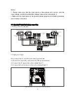
Страница 19: ...nal block 3C3 EX 20KS 30KS 40KS wiring connection 1 Wiring connection diagram 2 Single power input 12 Notes Please make sure that the input power is three phase with 4 wires and the input voltage is w...

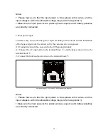
Страница 20: ...range refer to Appendix 1 Make sure the input power is the positive phase sequence and battery polarities are correctly connected 3 Dual power input Customers may choose the dual power input accordin...

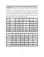
Страница 21: ...0kVA 16kW 10AWG 4mm2 10AWG 4mm2 6AWG 10mm2 10AWG 4mm2 6AWG 10mm2 3C3 EX 30KS 30kVA 24kW 6AWG 10mm2 6AWG 10mm2 4AWG 16mm2 6AWG 10mm2 4AWG 16mm2 3C3 EX 40KS 40kVA 32kW 6AWG 10mm2 6AWG 10mm2 1AWG 35mm2 6...

Страница 22: ...UPS number required for the total load and X is the redundant UPS number namely the malfunctioning UPS number that the system can simultaneously bear The larger X is the higher reliability of system w...

Страница 23: ...UPS input output should be connected to the same input patch board from which wires are distributed for load as illustrated in following gure 16 Remark 1 Common battery pack is applicable in parallel...

Страница 24: ...17 3 Parallel machine wire connection drawing 3C3 EX 20KS 30KS 40KS UPS 3C3 EX 60KS 80KS UPS...

Страница 25: ...ve the panel on the terminal bay and connect N and wires from UPS terminal bay to N and of the battery box make sure the battery polarities are correctly connected 4 Use multimeter DC Voltage to measu...

Страница 26: ...on the output of the battery bank 3 Switch on input breaker Line input breaker Main bypass input breaker Main line input breaker for 60K 80K standard models on the UPS and fans start to rotate for UP...

Страница 27: ...again to obtain the below 6 Press again to obtain the below information information 3 Press ESC to access or automatically 4 Press to obtain the below information access within 1min with no button bei...

Страница 28: ...n warning occurs will appear at the same position as illustrated in the below picture with battery mode as an example 7 Press again to obtain the below 8 Press again to obtain the below information in...

Страница 29: ...22 3 Select Yes Con rm to switch on 4 Normal Switch on the machine 5 Battery power supply switch off line input breaker 5 Switch off action press ESC to exit above picture...

Страница 30: ...1 Switch off picture 2 If it is in single machine mode the following will appear 3 If it is in parallel machine mode the 4 Press ENTER following will appear 5 Select Yes Con rm to switch off the machi...

Страница 31: ...mong the parallel machine system select single machine switch off if switch off is intended for the entire parallel machine system select parallel machine switch off 6 Help 1 Help picture 2 Press ENTE...

Страница 32: ...re You are able to access Setting picture by using user combination default 1234 subject to personal modi cation so as to set the following programs 1 Setting picture bypass power supply 2 Press 3 Inp...

Страница 33: ...elf inspection is completed 4 2 Parallel UPS operation Castle EX Series is capable of direct parallel connection customers can add additional machines on line to realize power redundancy and follow si...

Страница 34: ...ode all UPSs will transfer to INV mode Turn off when turn off is conducted under INV mode all UPSs will simultaneously turn off inverter and then transfer to the bypass mode if turn off the UPSs one b...

Страница 35: ...nication Interface exclusively available to Santak technical personnel 1 Intelligent slot suitable for WebPower card optional of remote supervising management enabling you to realize remote supervisin...

Страница 36: ...e power source management See Appendix for AS400 Port pin de nition 6 EPO emergency power off which provides users having emergency power off need with direct UPS output off function See Appendix for...

Страница 37: ...30 RS485 PORT Pin Description I O 3 RXDA Input 4 RXDB Input 5 TXDB Output 6 TXDA Output EPO external wiring diagram...

Страница 38: ...31 RS232 PORT Pin Description I O 2 TXD Output 3 RXD Intput 5 GND Output...

Страница 39: ...er When the UPS is applied to load devices there might be disturbances or malfunctions caused by the Neutral to Ground voltage However the installation of the special transformer to the output will ma...

Страница 40: ...ensitive to temperature the temperature sensor can be used to detect the temperature change enable the temperature compensation function of charge voltage the battery charge voltage will be adjusted a...

Страница 41: ...IP21 Option Castle EX 60 80K Series UPS adopts top perforation and top and bottom ventilation it is recommended to install the IP21 option to prevent objects with diameter larger than 12mm and water...

Страница 42: ...or performance replacement should be done as soon as possible only by quali ed personal with proper training Users are not allowed to replace without authorization Remark A Prior to battery replacemen...

Страница 43: ...iled failure description including LCD malfunction indicator condition buzzer information power and load capacity etc Table of Malfunctions Symptom LCD Display or Possible cause Solution The fault LED...

Страница 44: ...ode of battery power supply frequency output should bef0 1 of nominal Overload time 10min 110 Load 125 1min 125 Load 150 Ef ciency Double conversion mode Up to 93 Up to 94 ECO mode Up to 98 Operating...

Страница 45: ...2 min One beep every 2 min Fault One ashing every 4 sec One beep every 4 sec Overload One ashing every 1 sec One beep every 1 sec 3 Line Mode Normal None Fault One ashing every 4 sec One beep every 4...

Страница 46: ...sec Overload One ashing every 1 sec One beep every 1 sec 6 Fault Mode Normal Long light Long beep 7 Converter Mode Normal None None Fault One ashing every 4 sec One beep every 4 sec 8 ECO Mode Normal...

Страница 47: ...teries purchased from SANTAK 24 hour toll free helpline See the hot line number at the warning label located on the cabinet cover Nationwide warranty Technical support on our web site Toll free on sit...

Отзывы: