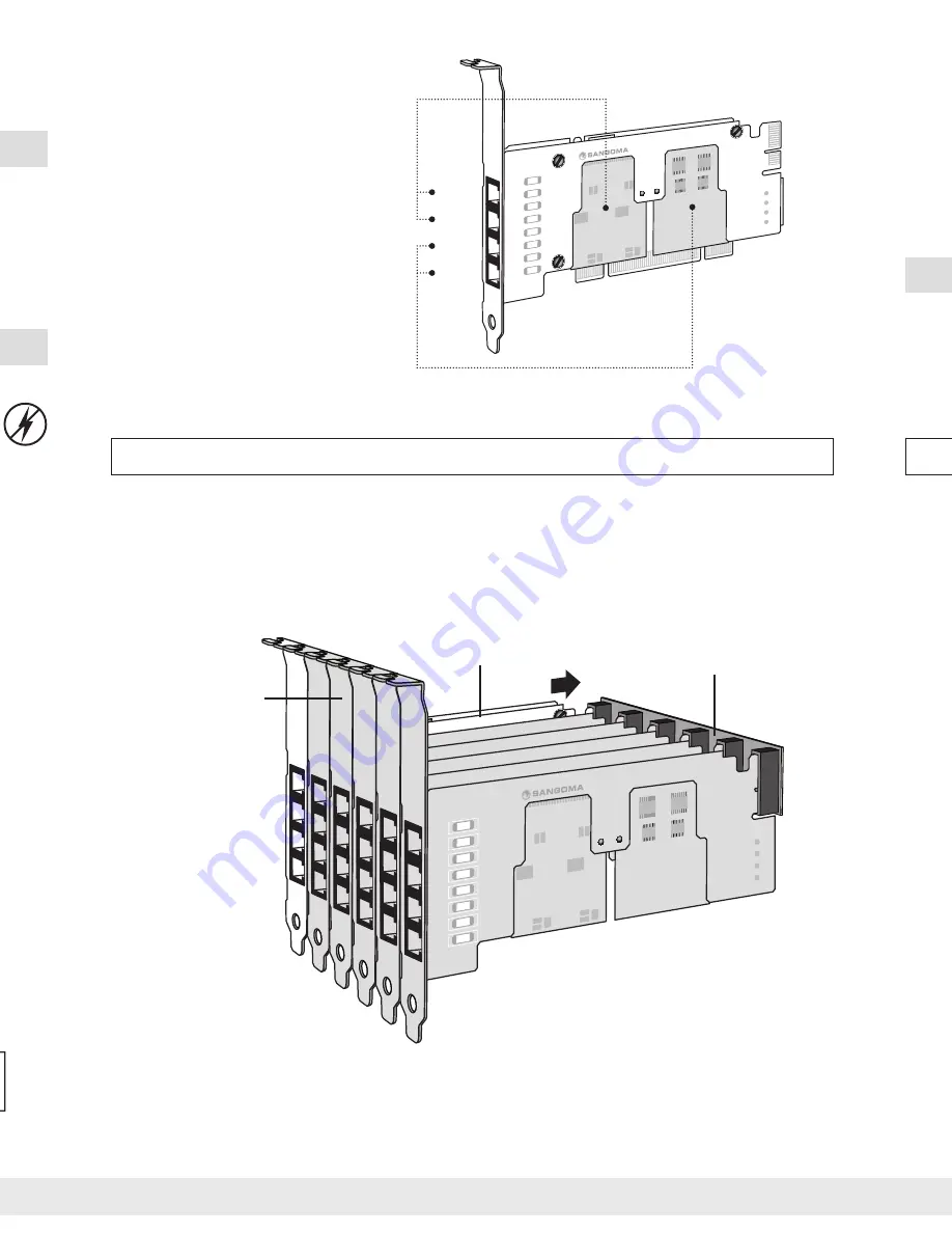
FXO-2
Port 1
Port 2
Port 3
Port 4
See diagram for corresponding
ports and module slots.
e.g.
The module inserted at Slot A corresponds
to Ports 1 and 2.
The module inserted at Slot B corresponds
to Ports 3 and 4.
Slot B
Slot A
C) Insert the card into an open PCI or PCIe slot in server.
Fasten PCI bracket to chassis.
A) Ensure you are grounded.
(i.e., Touch unpainted metal to avoid
destroying a computer with electrostatic
discharge, work on non-carpeted areas, etc.)
B) Carefully remove card and components from packaging.
Additional cards and components may be purchased separately.
Install your choice of supported software.
(e.g., Asterisk
®
, FreeSWITCH, Yate, CallWeaver, etc.)
See the list of compatible software at:
http://www.sangoma.com/products_and_solutions/compatible_software
Thank you for purchasing the Sangoma A200 card!
Please follow these instructions to begin using your new card.
2. INSTALL YOUR HARDWARE
1. INSTALL YOUR PBX SOFTWARE
Server
Server
PCI/PCIe Slots
A200: 2 - 24 Port Scalable FXO / FXS
Technical specifi cations available at WIKI.SANGOMA.COM
Full product specifi cations available at SANGOMA.COM
* If using one or more Remora daughter cards, you must attach a Molex
Power Connector from your computer’s power supply unit to the A200
main card.
When using FXS, you must always attach a Molex Power Connector
from your computer’s power supply unit, even for a small system with no
Remora. This is also recommended when using FXO on a small system,
but it is not necessary.
Visit
wiki.sangoma.com
for the latest drivers and instructions.
You're done! Enjoy your new card.
3. INSTALL THE DRIVERS (WANPIPE
®
CD)
Cable(s)
Analog Module(s)
or
FXO
FXO-2
FXS
Your A200 Card is fax synchronization ready.
Fax machines, connected to a PBX using PRI or BRI connection, run inconsistently at best,
simply because the analog interface supporting the fax machine is not synchronized to the
PSTN timing. Lack of a properly synchronized connection can result in faxes that are distorted,
missing lines and even fail outright.
To synchronize your new A200 to your digital card (A100-series or A500) simply connect the
jumper pins
†
on both cards via a two-wire jumper cable (each sold separately).
The digital card must have a HWEC (hardware echo canceller).
The minimum fi rmware that supports clock synchronization for the A200 is v10.
For more information, please go to
wiki.sangoma.com/t1e1analogfaxing
SYNCHRONIZE FOR FAX
(PATENT PENDING)
Jumper Cable
Red edge is at the top
Digital Card
A200 Card
Attach additional Remora card(s) using a backplane.
It is ideal to put the Remora(s) to the right of the main card, so that the main card always
contains port 1. However, if space is a concern, either side is appropriate.
The lowest number port on the backplane corresponds to port number 1 in the stack.
(e.g., JP6 on a 4-connector backplane.)
OPTIONAL – INSTALL UP TO 6 REMORA™ EXPANSION CARDS
FXO-2
FXO-2
Backplane
Install up to 6
additional Remora™
expansion cards
(24 ports in total)
Main Card
Recommended Confi guration Only
Port 1
Port 2
Port 3
Port 4
FXO-2
Optional Echo
Cancellation Module
A200 Card
Molex Power
Connector*
Full-height Bracket
Optional half-height
bracket included
Jumper Pins
†
Содержание A200 Analog
Страница 1: ...INSTALLATION MANUAL A200 Analog m...


