


KSwitch D1 UGPD Unmanaged Gigabit PoE Ethernet Switch - Preliminary User Guide, Rev. 0.9
// 27
5/
Mounting
Before installing the switch, consider the required orientation of the switch within the installation environment and
access to connectors.
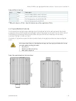
Mount leaving a clearance of 20 mm around the switch, to ensure proper operation and to
prevent the switch from overheating.
Restricted Access
The switch’s intended use is in a Restricted Access Location, where only authorized service
personnel or users can gain access. Such personnel must be instructed about the fact that
the metal chassis of the switch is extremely hot and may cause burns:
•
Service personnel or users have to pay special attention and take special precautions
before handling the switch.
•
Only authorized, well-trained professionals should be allowed to access the restricted
access location. Access should be controlled by the authority responsible for the
location with a lock and key or a security identity system.
Connect the switch only to a PoE network without routing to the outside plant or equivalent.
It is recommended to protect the switch by installing the switch in a RTU (Remote Terminal
Unit) or Protection Cabinet to avoid magnetic, heat, dust and water damaged.
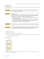
5.1.
DIN Rail Mounting
To mount the switch on a DIN-Rail, perform the following:
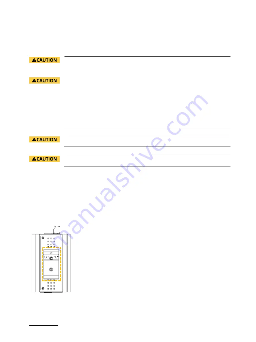
1.
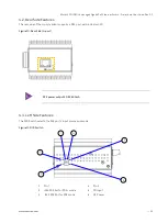
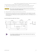
Fasten the DIN-Rail clip on the switch in the upper position (Figure 13) for the required mount orientation with the
screws (length 5 mm & size M3) provided
Figure 13: DIN-Rail Clip
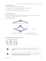
2.
Hook the top of the DIN-Rail clip over the DIN-Rail and push the bottom of the switch towards the DIN-Rail until
the Din-Rail clip snaps into place.


