
18
S&C Instruction Sheet 695-545
Operation
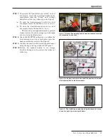
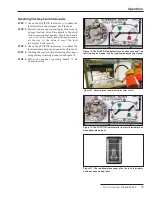
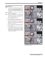
STEP 4.
Determine the phase-to-phase relationships of
the two ways to be phased as follows:
(a) Remove the test probe of the voltmeter from the
neutral jack.
(b) Place one of the test probes on Test Jack 1 of the
first way and place the other probe on Test Jack 1
of the second way. Measure the phase-to-phase
voltage. When comparing the
same
phase of the
two ways, the voltage should be 0.5 Vac or less for
system voltages through 13.2 kV maximum, and
between 0.5 Vac and 1.0 Vac for system voltages
through 29 kV maximum, indicating the cables
are in phase. See Figure 25 (a).
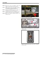
(c) Keep the test probe on Test Jack 1 of the first way
and move the other test probe to Test Jack 2 of
the second way. Measure the phase-to-phase
voltage. When comparing
different
phases of the
two ways, the voltage should be 1.7 to 2 times the
phase-to-neutral voltage measured in Step 3. See
Figure 25 (b).
(d) Keep the test probe on Test Jack 1 of the first way
and move the other test probe to Test Jack 3 of
the second way. Measure the phase-to-phase
voltage. Again when comparing different phases
of the two ways, the voltage should be 1.7 to 2
times the phase-to-neutral voltage measured in
Step 3. See Figure 25 (c).
(e) Repeat Steps 4b through 4d for Test Jack 2 and
Test Jack 3 of the first way.
(f) If all the phase-to-phase relationships are
correct, the cables are in phase and are properly
installed.
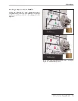
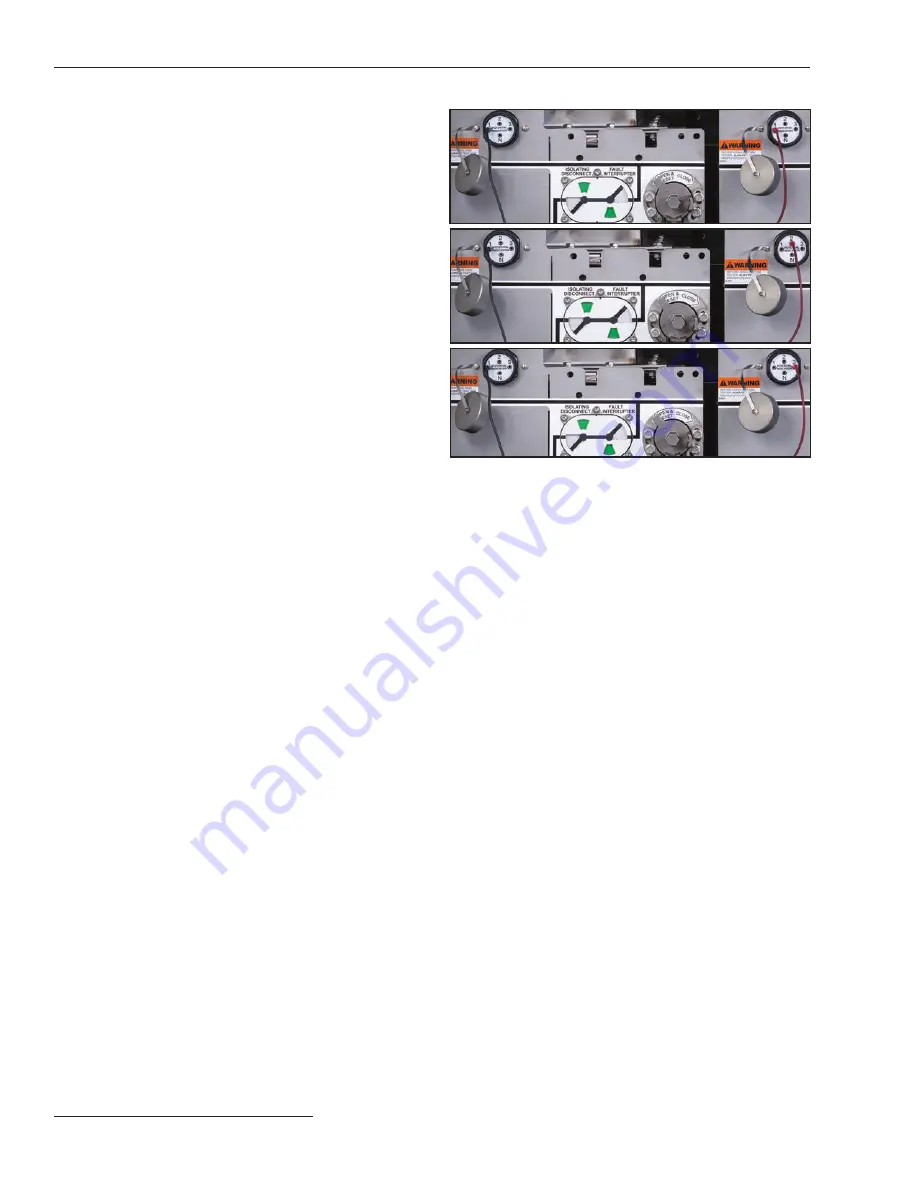
Figure 25. Measure the phase-to-phase relationships of the two
ways to be phased. When comparing the same phase of the two
ways, the voltage should be zero or close to zero, indicating the
cables are in phase. When comparing different phases of the two
ways, the voltage should be 1.7 to 2 times the phase-to-neutral
voltage measured in Step 3.
(a)
(b)
(c)