


S&C Instruction Sheet 695-545
11
Operation
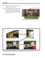
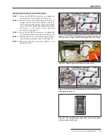
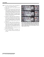
Figure 8. Indicators and mimic bus show the position of the load-
interrupter switch or fault interrupter.
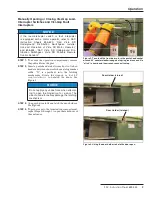
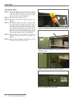
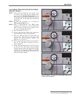
Figure 7. Rotate the operating handle counterclockwise to open
(a), clockwise to close (b).
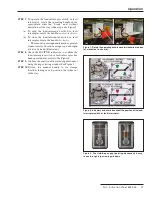
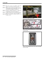
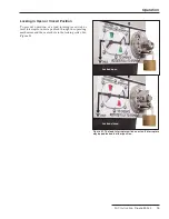
Figure 9. The visible-open gap (isolating disconnect) is easy
to see through large viewing windows.
STEP 7.
To operate the load-interrupter switch or fault
interrupter, rotate the operating handle in the
appropriate direction fi
rmly, and without
hesitation, all the way to the stops. See Figure 7.
(a) To open the load-interrupter switch or fault
interrupter, rotate the handle
counterclockwise.
(b) To close the load-interrupter switch or fault
interrupter, rotate the handle
clockwise.
The manual operating handle may be operated
from a variety of locations using a rope, a shotgun
stick, or by hand (illustrated).
STEP 8.
Check the POSITION indicators to confi rm the
load-interrupter switch or fault interrupter has
been operated successfully. See Figure 8
STEP 9.
Confi rm the position of the isolating disconnect
using the large viewing window. See Figure 9.
STEP 10.
Return the manual handle to its storage
location, taking care to position the tether out
of the way.
(a)
(b)