


English
_7
● OVER
VIEW
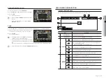
PART NAMES AND FUNCTIONS (FRONT)
XRN-2010
XRN-2011
Part Names
Functions
LED Indicator
REC
: Lights on when recording is in progress.
HDD
: Displays the normal access to HDD.
LED turns on when accessing the hard disk.
ALARM
: Lights on when an event occurs.
NETWORK
: Displays both network connection and data transfer status.
BACKUP
: Stays ON when backup is in operation. (XRN-2010)
RAID
: Stays ON when RAID is in use. It flickers if backup is activated when RAID is in use.
Flickers only when backup is in operation if RAID is not in use. (XRN-2011)
POWER
: Shows the power ON/OFF status.
b
USB
Connects the USB devices. (USB 2.0 supported)
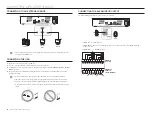
PART NAMES AND FUNCTIONS (REAR)
Part Names
Functions
Ground connection
Terminal to connect a separate ground cable.
`
Add a ground cable to support the safe use of the device.
b
VGA OUT
VGA Video Signal Output Port.
c
ALARM
-
ALARM IN : Alarm input ports. (1~8 CH)
-
ALARM RESET : Alarm Reset port
-
ALARM OUT : Alarm output ports. (1~4 CH)
eSATA
Terminal to connect an external storage device.
NETWORK1
Port recommended for camera connection, which receives an image from the camera.
NETWORK2
Port recommended for connection with a network, web viewer or iSCSI.
AUDIO OUT
Audio Signal Output Port (RCA jack).
RS-232C
Cable terminal for serial communication (spare).
HDMI
HDMI connector port.
USB
Connects the USB devices. (USB 3.0 supported)
Power
Terminal to connect power to.
M
`
[
CONSOLE
] is designed for the service repair purpose only.
USB
NETWORK VIDEO RECORDER
b
USB
NETWORK VIDEO RECORDER
b
HDMI
USB
eSATA
RS-232C
VGA OUT
AUDIO OUT
NETWORK 2
NETWORK 1
CONSOLE
1 2 3 4 5 6 7 8
NO
COM
COM COM COM
NC NO NO
NO
1
2
3
4
ALARM IN
ALARM OUT
G
G
ALARM
RESET
c
b


