background image

13

Operation

C

h

a

p

te

2

-.---.-.-.-----.---.-.-.

---..-.---.-..---.----

---.----.---.-.-...---.-.

---..-.---.-..---

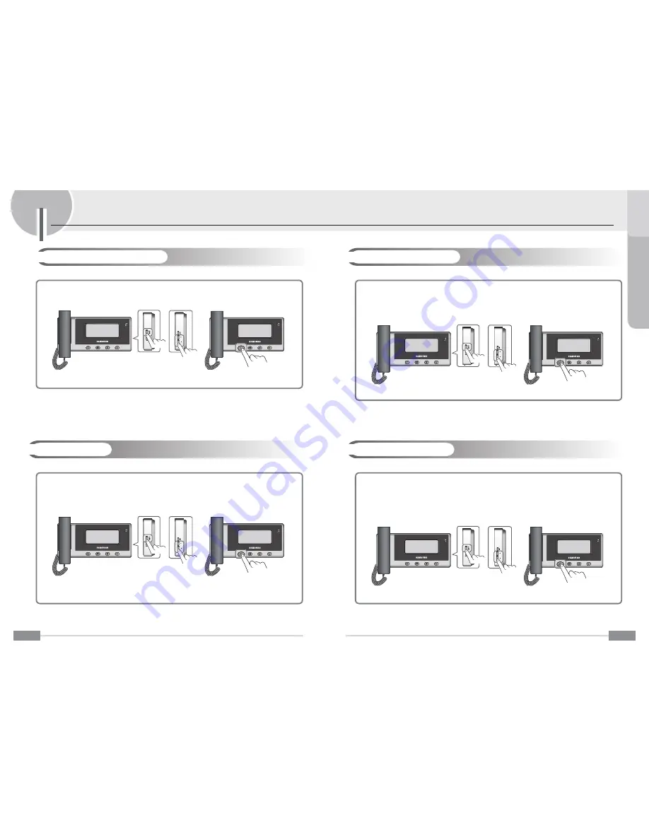
1. During the Supervisor setting mode, press the 

SET

 button repeatedly to select 

4.MULTI LOBBY SET

.

2. Press the 

+

 / 

-

 buttons repeatedly to select the 

SET

, or 

RELEASE

.


SET 

: The DOOR2 port is connected the multi panel.


RELEASE 

: The DOOR2 port is connected the door camera.

3. Press the  

Interphone

 button to store your setting.

-.---.-.-.-----.---.-.-.

---..-.---.-..---.----

---.----.---.-.-...---.-.

---..-.---.-..---

Set to activation of the Multi Panel mode.

After connecting to the Multi panel instead of the DOOR2, be sure set to “SET” on the 4.MULTI LOBBY SET item.  
The DOOR2 monitoring function is disabled.

-.---.-.-.-----.---.-.-.

---..-.---.-..---.----

---.----.---.-.-...---.-.

---..-.---.-..---

1. During the Supervisor setting mode, press the 

SET

 button repeatedly to select 

5.DOOR1 OPEN SET

 or 

6.DOOR2 OPEN SET

.

2. Press the 

+

 and 

-

 buttons repeatedly to select the 

MAIN

 or 

CAMERA

.


MAIN 

: The LOCK1/2 port is connected the door lock.


CAMERA 

: The LOCK1/2 port is connected the door camera

3. Press the  

Interphone

 button to store your setting.

-.---.-.-.-----.---.-.-.

---..-.---.-..---.----

---.----.---.-.-...---.-.

---..-.---.-..---

Setting the Door Open

Set to a door lock or door camera function for the Door1/2 port.

After connecting to the door lock or door camera to the LOCK1/2 port, be sure set to “MAIN” or “CAMERA” on the 5/6.
DOOR1/2 OPEN SET item. If the DOOR1/2 OPEN SET is CAMERA, the door lock’s open function is disabled .

Setting the Multi panel

12

These functions are used to customize some product functions in the user’s environment.

4VQFSWJTPSTFUUJOH'VODUJPOT

-.---.-.-.-----.---.-.-.

---..-.---.-..---.----

---.----.---.-.-...---.-.

---..-.---.-..---

1. During the Supervisor setting mode, press the 

SET

 button repeatedly to select 

2. CAMERA QUANTITY

.

2. Press the 

+

 / 

-

 buttons repeatedly to select the 

1

, or 

2

.

3. Press the  

Interphone

 button to store your setting.

-.---.-.-.-----.---.-.-.

---..-.---.-..---.----

---.----.---.-.-...---.-.

---..-.---.-..---

Set to the camera quantity for the monitoring function.

After connecting to the cameras, set to be sure correctly that you connected all cameras quantity.
Do not set incorrectly, it may cause malfunction of the monitoring. 

-.---.-.-.-----.---.-.-.

---..-.---.-..---.----

---.----.---.-.-...---.-.

---..-.---.-..---

1. During the Supervisor setting mode, press the 

SET

 button repeatedly to select 

3. BELL SET

.

2. Press the 

+

 and 

-

 buttons repeatedly to select the 

SET

 or 

RELEASE

.


SET 

: The BELL_1 port is connected the door bell.


RELEASE 

: The DOOR1 port is connected the door camera.

3. Press the  

Interphone

 button to store your setting.

-.---.-.-.-----.---.-.-.

---..-.---.-..---.----

---.----.---.-.-...---.-.

---..-.---.-..---

Setting the Bell

Set to activation of the door bell mode for the DOOR1 port.

After connecting to the bell instead of the DOOR1, be sure set to “SET” on the 3.BELL SET item and the DOOR1 port 
can not connect to nothing.

When the BELL SET is SET, call time is set 30 seconds, door open function is activated, talk and monitoring functions 
are disabled.

Setting the Camera Quantity

Содержание SVD-4332

Страница 1: ...Z6806140601A GC68 01539A ED 02 ...

Страница 2: ......

Страница 3: ...pes of wastes and recycle it responsibly to promote the sustainable reuse of material resources Household users should contact either the retailer where they purchased this product or their local government office for details of where and how they can take this item for environmentally safe recycling Business users should contact their supplier and check the terms and conditions of the purchase co...

Страница 4: ...etting the Open Time 14 Setting the Call Time 14 Setting the Talk Time 15 Setting the NAND Flash Bulk Check 15 Setting the Video mode 16 Initializing the Supervisor mode 16 Setting the Chroma Delay 17 Setting the Stroage Image Number 17 Visitor Image Functions Auto recording of missed visitor images 18 Recording visitor images manually 18 Replaying stored images 19 Deleting the current image 19 Ch...

Страница 5: ...n death or serious injury Neglect to follow directions can result in injury or material loss 8BSOJOH BVUJPO Do not place the product near a heat source e g heater or source of moisture e g aquarium humidifier It may cause product malfunction and or fire Do not subject the product to any heavy shock such as striking with a hard object e g hammer etc It may cause product malfunction electric shock a...

Страница 6: ...n replace the interphone handset to hang up a call PUF ⷅ If the current call is switched to speakerphone mode by pressing the Call button in handset mode you can continue the call in speakerphone mode after replacing the handset BNFT BOE VODUJPOT 4 ⶺ Product Monitor ⴘ BOETFU This is used to communicate with a visitor outside the entrance or the common entrance or make calls to the interphone ⴙ TDS...

Страница 7: ...placing the handset PUF 6 These functions enable you to check the status outside the entrance OUS BODF VODUJPOT If you repeatedly press the Call button the entrance hall images are displayed in turn If you press the Call button in standby mode the entrance image is displayed on the screen and a call is connected ⷅ If you press the Call button with the handset picked up the phone is connected in ha...

Страница 8: ...K VOLUME 2 8 ⶺ Entering for user setting mode These functions are used to customize some product functions in the user s environment 6TFS 4FUUJOH VODUJPOT Select a desired setting mode by repeated pressing the SET button in standby mode Press button to enter the selected mode ⷅ To exit the user setting mode select D EXIT and then press the Interphone button to save your settings In addition if the...

Страница 9: ...function of the master or the slave unit ⷅ To save and exit your settings press the Interphone button These functions are used to customize some product functions in the user s environment 10 These functions are used to customize some product functions in the user s environment 6TFS 4FUUJOH VODUJPOT 1 During the standby mode press the SET button repeatedly to select the 5 ALL IMAGE DELETE 2 Press ...

Страница 10: ...ET is CAMERA the door lock s open function is disabled ⶺ Setting the Multi panel 12 These functions are used to customize some product functions in the user s environment 4VQFSWJTPS TFUUJOH VODUJPOT 1 During the Supervisor setting mode press the SET button repeatedly to select 2 CAMERA QUANTITY 2 Press the buttons repeatedly to select the 1 or 2 3 Press the Interphone button to store your setting ...

Страница 11: ...bulk check function enable or disable ⶺ Setting the Talk Time 14 These functions are used to customize some product functions in the user s environment 4VQFSWJTPS TFUUJOH VODUJPOT 1 During the Supervisor setting mode press the SET button repeatedly to select 7 DOOR1 OPEN TIME SET or 8 DOOR2 OPEN TIME SET 2 Press the buttons repeatedly to select the desired time 1SEC 10SEC 3 Press the Interphone bu...

Страница 12: ...ly to select the YES or NO Yes Perform the initialization No Cancel the initialization 3 Press the Interphone button to store your setting ⶺ Initializing the Supervisor mode 1 During the Supervisor setting mode press the SET button repeatedly to select the N VIDEO MODE SELECT 2 Press the buttons repeatedly to select the NTSC or PAL 3 Press the Interphone button to store your setting Set to the vid...

Страница 13: ...re used to record store visitor images 7JTJUPS NBHF VODUJPOT If a call by a visitor is disconnected by not answering the call within CALL TIME by supervisor setting the visitor s image is recorded stored automatically ⷅ The recorded stored images can be replayed checked deleted in visitor image replay mode ⷅ The calling visitor s images are automatically recorded stored in absent status or during ...

Страница 14: ...lines 2 Do not install in a place with too high or too low temperatures if possible ⷀ SVC 0270P ⷀ SVC 0271M ⷀ SVC 0270M 20 OTUBMMBUJPO 1S PEVD U OTU BMMBUJPO S BXJOH Installation method and height of Monitor ⶺ Monitor 1 Select a place to install the product Install the product and place the center of the Monitor at a height of 145 cm from the floor 2 Fix the wall mount bracket on the selected plac...

Страница 15: ...ervisor mode to select 1 ID SET SLAVE1 3 Press the and buttons to select the SLAVE1 4 Press the Interphone button to save and exit To set the connected unit to SLAVE device be sure set to the SLAVE ID without overlap If the SLAVE ID is overlaped the unit may malfunction PUF 22 ⶺ 4 Monitors 2 Door cameras 2 Door locks For safety and correct product connection always install the product as shown in ...

Страница 16: ...or Lock 1 RED DOOR LOCK 2 BLACK Monitor VS Bell 1 RED Door Bell 2 BLACK 24 8JSJOH For safety and correct product connection always install the product as shown in the wiring diagram below ⶺ 4 Monitors 1 Door camera 1 Multi panel ⶺ 1 Monitor 1 Doorbell 1 Door lock PUF ⷅ If a doorbell is connected the DOOR1 port does not connect anything ⷅ If a doorbell is connected be sure set the BELL SET item of ...

Страница 17: ...s refer to page 9 The screen brightness settings consist of 4 phases and factory default set is 2 There is too much noise during calls ⷅ Check to see if the door phone line has been short circuited with the ground Calls are not audible ⷅ Check the volume setting ⷅ Check the wire connection between the monitor and the camera 26 The product packages are as shown in the figure below Check they contai...

Отзывы: