background image

44 


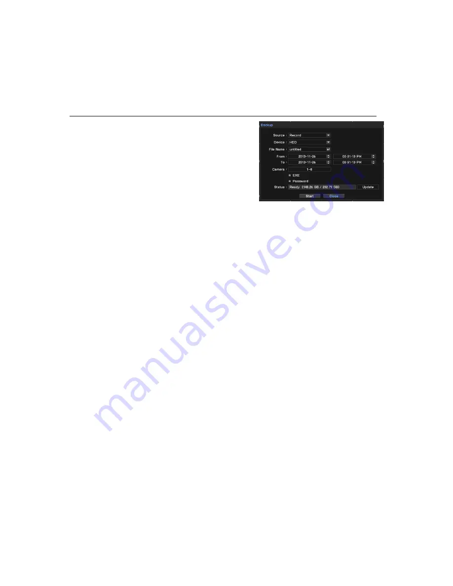
BACKUP 


Backup Recorded Data 

1.  Click right mouse button on live mode 

2.  Select Backup and choose type.(backup or AVI 

maker) 

3.  Insert USB memory on system USB slot. 

4.  Select Device for backup data(generally USB 

memory is used) 

5.  Set backup data period and camera. 

6.  Select ‘EXE’ option and ‘Password Option. 

7.  Press ‘Start’ button. 

Backup’ data saved as ‘strg, exe’ format and requires exclusive player for multi channel 

playback.   

For Single channel backup, use AVI backup.   

Do not remove backup media while data backup is being processed


Содержание SRM-872

Страница 1: ...1 NETWORK VIDEO RECORDER UserManual SRM 872 ...

Страница 2: ...t no formal guarantee shall be provided Use of this document and the subsequent results shall be entirely on the user s own responsibility Samsung Techwin reserves the right to change the contents of this document without prior notice Design and specifications are subject to change without prior notice The initial administrator ID is admin and the password should be set when logging in for the fir...

Страница 3: ...t from the apparatus 11 Only use attachments accessories specified by the manufacturer 12 Use only with the cart stand tripod bracket or table specified by the manufacturer or sold with the apparatus When a cart is used use caution when moving the cart apparatus combination to avoid injury from tip over 13 Unplug this apparatus during lightning storms or when unused for long periods of time 14 Ref...

Страница 4: ... antenna installation is wrong it receives unstable data Normal GPS error distance is 16m in stop 30m in moving WARNING Caution Power off before installation to extend power cord use AWG American Wire Gauge 18 or thicker When Install GPS antenna attach it on flat place outside of vehicle with accessories GPS antenna must head to the air Wrong installation causes unstable data receiving GPS error r...

Страница 5: ...low the guaranteed one Ethernet Port This equipment is indoor use and all the communication wirings are limited to inside of the building Security Precautions The initial administrator ID is admin and the password should be set when logging in for the first time Set password for your wireless network if you use the product with a wireless router Being not protected with password or using the defau...

Страница 6: ...veillance Start END system 17 Log in 17 Shutdown system 18 Live monitoring screen 19 OSD icons 19 Contextual Menu on Live 20 Live screen division 20 Single Channel Live view 20 Backup 21 Live Monitoring 21 Recording Status 21 Emergency Recording 21 Move to Search mode 21 Enter Setup Menu p22 System Setup 22 System Information 25 User Setup 27 Device 29 Profile SETUP 30 Audio 31 Alarm 32 Display 34...

Страница 7: ...p45 Web Client Access p47 Smartviewer Auto v1 0 52 Smartviewer AUTO v1 0 Setup p55 Callback p56 Mobile viewer iPolisAuto p58 Appendix 58 System Specification 60 Default Configurations 62 IO BOX Installation 63 Connector Pin Map 66 FAQ ...

Страница 8: ...ouse and external storage HDD SSD and Micro SD support Mobile device support IPhone and Android Digital zoom Compact size for vehicle installation Backup storage support such as USB memory stick Built in GPS E Map support Industrial standard in Enduring Temperature limit Built in power support PoE Apply military product level test in vibration and shock test I O Box Sensor Alarm G Sensor Status LE...

Страница 9: ...ed in product box NVR Main unit IO BOX Control Box Power cable 1ea RS232 connect cable 2ea RJ45 UTP cable 2ea GPS Antenna Remote Control Battery CD User manual Quick Guide HDDfixscrewandKey Rear cover Part color and design may differ due to the manufacture ...

Страница 10: ...external storage 3 Audio output Sound output as line output 4 Video output Connect VGA monitor to view display 5 HDMI output Connect HDMI monitor 6 RESET switch Use when restart system 7 Micro SD Slot Insert Micro SD for recording 8 IR sensor Receives signals from remote controller 9 LED Display NVR status 10 Lock Key Lock HDD device This must be locked to start system ...

Страница 11: ...as System supports power over Ethernet when use PoE IP camera 2 NETWORK Connect network cable for CMS and Web view 3 CONTROL BOX Connect to control box 4 IO BOX 1 Connect to IO box 5 PWR Connect power supply from vehicle 6 GPS Connect GPS Antenna SMA type ...

Страница 12: ...on status of IO BOX 2 Dip Switch Set moving direction of vehicle name Description 1 GND Ground connection Connect to vehicle body 2 IO BOX 1 Connect to main unit s port 3 ALARM Connect to speed pulse of the vehicle This port can be used for RS232 485 4 SENSOR Connect Alarm output to External devices Additional power required Open collector type ...

Страница 13: ... storage HDD SD storage is available Light on when storage HDD SD is not available Light on GPS position fixed after receiving data Light on when Shutdown delay is processing Light on when alarm output is working 3 IR receiving ports Receives IR signals from remote controller name Description 1 Audio out Audio Line out 2 Control box Connect to main unit s control port ...

Страница 14: ... main unit and bracket with screw 2 in picture 3 Assemble rear cover and main unit with screw 3 in picture The cables must be passed through rear cover hole as following picture 4 Tied up installed cables firmly Mount product Use 6 screws as following picture and mount brackets on installation place ST 15kgf ST screw tightening power Tighten screw with recommended torque ...

Страница 15: ...15 Install IO Control box Connect IO box and Control box with provided cable as above picture ST screw tightening power Tighten screw with recommended torque ...

Страница 16: ...unit to the bracket which installed on bottom with 6 screws Caution When installed on bottom it may cause HDD shock issues For the torque of screws see the pictures on previous page ST torque of screws Each tool has differ torque you should follow guided torque when installation ...

Страница 17: ...initial screen and start initializing 3 It shows login screen 4 To log in select admin and press OK No password is configured at initial time if there s configured password click password field and use virtual keyboard see picture 5 System logs in as Administrator Note password can be set up to 8 numbers with combination of number 0 to 9 Special character are not allowed To enter new password go t...

Страница 18: ...rn on when sequencing mode works Turned on when HDD is set as overwrite mode Turned on system receiving GPS data Turned on network connected Turned on when alarm is activating Turned on with G Sensor detects events Turned on Emergency Recording is on 4 Time date info Display time date information 5 Remote controller Turned on when IR remote controller is activating Remote controller can control sy...

Страница 19: ...cription No Recording greed Pre Event Rec blue Recording Red Motion Detection Emergency Recording Sensor Detection Event Recording red IP Camera event Detection High Resolution Playback name Description 1 Camera Select camera and display 2 Layout Select screen mode 3 Live Monitoring Display IP camera images 4 Record Monitoring Display real time recording status 5 OSD OSD display options 6 Sequence...

Страница 20: ...ouse button and it display single channel view of selected channel 2 Press desired channel number on remote controller and it display single channel view of selected channel 3 Click right mouse button on live view and select Camera then select desired channel 4 Double click again back to previous mode Backup 1 Click backup button on remote controller 2 Click right mouse button and open contextual ...

Страница 21: ...ording Record immediately on live mode 1 Press Emergency Rec button on control box It turns red 2 Press E REC button on remote controller 3 Or use contextual menu click right mouse button and select Emergency Rec Move to Search mode 1 Click Right mouse button on live mode and open contextual menu 2 Select Playback mode Enter Setup menu 1 Click Menu button on remote controller 2 Click Menu button a...

Страница 22: ...can export Import and set default system setup To export import USB memory is required 5 Back to default with Default button Date Time User info Display Resolution Language Network Setup IP address DDNS will not be initialized 6 Press OK to save changes Enter Vehicle information 1 Press Menu and move to SYSTEM Information 2 Enter necessary information 3 Shutdown delay After ignition off system wai...

Страница 23: ...1 Press menu move to System Date time 2 Set time zone and choose option daylight saving time Configure Beginning and End day 3 Set date and time with display format selection 4 Press OK to save changes NTP setting 1 Select NTP tab menu on Date Time setup menu 2 Tick Use NTP option 3 Press to enter time server 4 Enter time server name with virtual keyboard 5 Set update interval and press update but...

Страница 24: ... or days as holiday and apply different recording schedule 1 Move to Holiday tab menu on Date time setup 2 Press button and set date 3 Press OK to apply setup Note Holiday may not same date every year User may have to update every year ...

Страница 25: ...ord for new user Auto Login Log in automatically with selected user Auto Logout Log out when there is no action during configured time Add new group and set permission Administrator can define authority on each group not per user 1 Go to System User menu and select Group 2 Press button 3 Enter new group name 4 Set permission on new group Set camera channels on each authority if necessary 5 Click O...

Страница 26: ...STEM Log 2 To view latest log press Reload button and update logs Use button to move next pages To Export Log file 1 Prepare USB memory 2 Insert connect USB on system and move to System Log page 3 Press Export button 4 Set file name and press OK button Note log file exports as csv file format ...

Страница 27: ... new camera name IP camera setup Enter IP camera information and authorize it to check its working status 1 Press IP Address on camera menu 2 Enter IP ports and ID Password of desired IP camera 3 Check Authentication and press Connect to check IP camera connection status 4 Once Log in success message means it connects normally If it fails check information again 5 Press OK to save information ...

Страница 28: ...ive monitoring Fps number of frames for live monitoring Kbps image data size for live monitoring 3 Press Edit button to edit profiles 4 Press OK to save changes Covert Hidden camera Covert Hide camera on live view according to logged in user 1 Press Menu and move to DEVICE Camera page 2 Move to Covert tab menu 3 Set schedule on From To field 4 Select covert mode Low mode No display but OSD High mo...

Страница 29: ...le Menu Device Camera Live profile Record Profile Menu Recording Recording Record profile Network Profile Menu Network Transmission Network profile Add profiles 1 Select one of profiles from Live Recording and Network and move to that menu 2 Press Edit button on right and it shows current profile details 3 To add new profile press button below and set profile name codec resolution fps and Kbps inf...

Страница 30: ...Connect NVR records sounds on each channels 1 Press Menu and move to DEVICE Audio page 2 Select audio channel and change title as desired name 3 Press OK to save changes Note Audio input is only available with camera ...

Страница 31: ...rm channel and change title as desired name 4 Choose type of alarm NO Normal Open NC Normal Close 5 Press OK to save changes Set Alarm Schedule 1 Move to Schedule tab 2 Select Day and time for alarm activation 3 Select mode Event On Off 4 Select alarm output number and buzzer options 5 Press OK to save changes If schedule is overlapped the latest one will have priority ...

Страница 32: ...resolution select Resolution menu and select desired one 4 Press OK to save changes Channel popup by Event Display popup event triggered channel for a configured time 1 Press Menu and move to Display Monitoring page 2 Set Sequence interval time 3 Check Event popup option 4 Select camera number to be displayed when event occurred 5 Press OK to save changes ...

Страница 33: ...enu and move to Display PIP page 2 Set Size and Position 3 Press OK to save changes Note PIP is only available on single live display Resolution setup 1 Press Menu and move to Display resolution page 2 Set resolution 3 Press Ok to save changes ...

Страница 34: ...ord shows data stored period and HDD usage Recording Setup 1 Press Menu and move to Record Record 2 Check Overwrite option If not selected system only records data until the current HDD is full Time Record is continuous recording Event record is record only when event triggered Emergency Record Activated by Emergency Rec signal from outside 3 Press Ok to save changes Recording profile Select profi...

Страница 35: ...rd until off Emergency Rec 4 Event record duration is for general event recording duration 5 Press OK to save changes Set Recording schedule 1 Press Menu and move to Record Record Schedule tab 2 Set day option on day field One selected day option on each line 3 Set time to record on From To field 4 Select recording mode 5 Select cameras to be applied To delete schedule press button on right ...

Страница 36: ...k and Gateway 4 Press OK to save changes To change communication port move to PORT page in this menu PoE Setup Power Over Ethernet 1 Press Menu and move to Network Address PoE page 2 Set IP address and Subnet mask 3 Check DHCP server option When use this system as DHCP server must set IP ranges which will assigned to connected IP cameras connected camera should be set on DHCP option 4 Press Ok to ...

Страница 37: ... port Default is 554 5 Use UPnP This feature enables auto port forwarding on router DDNS setup For remote access use DDNS service with DDNS server setup 1 Press Menu and move to Network DDNS 2 Check Use DDNS option 3 Enter Product ID and press Update to check it access DDNS server normally 4 Press Ok to save changes To use DDNS system should be connected to Internet For more details about DDNS set...

Страница 38: ...new event as callback message after interval 3 Enter IP address that would receive callback messages 4 Press Ok to save changes Callback utility is installed when you install Remote client software Email setup 1 Press Menu and move to Network Notification Email page 2 Set E mail interval not send event between interval time 3 Check image option to attach on email 4 Enter e mail address of receivin...

Страница 39: ...on and optimize it 1 Press Menu and move to Network Transmission Transmission page 2 Set network bandwidth according to you network speed 3 Press Ok to save changes Network profile Select profile for live monitoring See details for profile section before Audio ...

Страница 40: ...llback or E mail Example1 Sensor setup Once sensor 1 is triggered record channel 1 2 alarming 1 2 4 and send Notification 1 Press Menu and move to Event Sensor page 2 Tick Sensor1 and set type NO or NC 3 Click Record tab and click sensor1 Record field and select channel 1 2 4 Click Alarm tab and click sensor1 Alarm field and select channel 1 2 4 5 Click Notification tab and click sensor1 Notificat...

Страница 41: ...acceleration stop and suspected as accident 1 Press Menu and move to Event G Sensor page 2 Check Use G sensor 3 Press Record field and select channels to be recorded when event triggered 4 Press Alarm field and select channels for alarm activation 5 In Notification field select Client IP address and e mail that will receive event notification 6 Set sensitivity of each x y and z axis If G sensor in...

Страница 42: ...et time and move to specific time Go to Beginning move to the first recorded data Go to End move to the end of data Go to sec move to previous recorded data data before When playback recorded data it displays single channel image which is close to search condition Calendar Search 1 3 Same as Time Search 4 Click right mouse button again and select Calendar 5 Select date and time and press Go To 6 D...

Страница 43: ...ent page System writes event log when it is set as Event recording Backup data playback 1 Click right mouse button on live mode 2 Select Backup data 3 Select Device and files 4 System displays playback screen Use playback control button below Backup playback is only available if there s backup file Playback control R Play Reverse Playback 1x 2x 64x 1x Step Backward Go to the previous image Pause F...

Страница 44: ...lot 4 Select Device for backup data generally USB memory is used 5 Set backup data period and camera 6 Select EXE option and Password Option 7 Press Start button Backup data saved as strg exe format and requires exclusive player for multi channel playback For Single channel backup use AVI backup Do not remove backup media while data backup is being processed ...

Страница 45: ... Enter ID and Password in log in page 3 Press buttons Live playback and move to new windows 4 Use following buttons to do data search Button Description Button Description Select camera Event search Remote setup FW Rev Playback Entire scren 2 64x playback Change layout Move 1 frame Select calendar Move to first last Pause ...

Страница 46: ... software See Smart viewer part on next page If no Active X installed run explorer with Run as Administrator option To upload file on IE internet Explorer set options on Tools Internet option Security Customer level supported on IE7 0 or higher ...

Страница 47: ...mote software 1 Press Connect icon to display connection list 2 Press Add and NVR information that desired to connect Name Enter NVR name Address Enter NVR s IP address Port Default is 10101 If changed enter changed port Description Optional enter comment User select NVR user account Password enter password for NVR user 3 Click OK to save information and complete the registration 4 Press double cl...

Страница 48: ...Add button 4 Enter group name and description 5 Select Layout and choose layout 6 Click site field and select one of site and camera Only Registered site can be displayed NVR status Click buttons on right side to display to display NVR status It shows NVR status as follows Reload Refresh the latest NVR status info Reset Alarms Turn off activated Alarms on the NVR ...

Страница 49: ...emote Playback Search 1 Press search button and connect NVR with connect button 2 Select date on calendar and time on screen 3 Playback image with control buttons Button Description Move to the first Reverse playback 1 64x 1 frame move to backward Pause 1 frame move to forward Forward playback 1 64x Move to the end In search mode it displays a channel image of the closest time Audio playback is on...

Страница 50: ...control buttons Event Search 1 Press event search icon in playback mode 2 Select the date event type and camera 3 Then select one of event desired to playback Saves recorded data 1 Move to Playback mode 2 Click icon and select Backup strg or exe 3 Specify file name duration and camera strg requires remote s w to playback ...

Страница 51: ...n PC 3 Run Remote s w on PC run as administrator 4 Click button and move to Storage tab to display HDD data Click Reload button to refresh data 5 Double click one of list and click Connection button Run Smartviewer AUTO v1 0 as Run as administrator to display recorded data list on Storage tab In Higher version than Widows Vista To supply enough power use cables as below picture Double USB port req...

Страница 52: ...Live if the connections is ended by any chances Load Load saved data for settings for remote software Save as Save current settings of remote software Default Set default settings of remote software Log Displays logs Display Maintain Aspect Ratio 4 3 Keep 4 3 ratio on display screen Use Alpha Blending Enables alpha blending effect to S W UI Video Acceleration Enhances natural live image display Do...

Страница 53: ...dd to sequence list 4 To move all sites click button 5 Set sequence duration interval time Only selected sites can be sequenced on live monitoring User setup 1 Move to User tab on setup 2 Press Add button to add user 3 Enter user name and set password 4 Check necessary permissions on list 5 Press OK 6 Select newly added user and his authority is correct ...

Страница 54: ...ay connected device s setup screen as same as local device Setup menu and usage is same as local device 4 To exit setup press menu exit Remote upgrade 1 Prepare upgrade file from your provider 2 Go to Remote Setup and move to System Information page 3 Press Upgrade button and select upgrade file 4 Proceed upgrade Do not close or power off system until the upgrade process is over ...

Страница 55: ...allback icon to display Callback window 4 To connect NVR select a log and click live or playback icon below Clear clear all logs on callback window Log Open log search window up to 100 000 logs can be saved 1 000 logs display per search To see more click More button To export press export and save logs txt or csv format Setup Set port for call back UDP port needs to be set open to transmit Callbac...

Страница 56: ...ct site and connection mode In iOS use buttons to add edit and delete site list Displayed lists are the registered NVR site and Auto button will display the NVRs which are searched on network Select connection mode on below Live Playback Setup 2 Live mode Android Description iPhone Camera displays current camera list and select desired channel to see live view Event Display NVR s live events Alarm...

Страница 57: ... desired event or time to load recorded data and you can control playback with control buttons Max 4 channels can be playback in same time and 1 32x speed control available In Event search playback use button and select option to playback desired event and camera 4 Setup configuration Android Description iPhone Same Setup UI provided on mobile device like local NVRsetup Not available these feature...

Страница 58: ...peed Up to 1Gbps Max Remote users Live 10 Search 3 Setup 1 Protocol support TCP IP DHCP SMTP NTP HTTP DDNS RTP RTSP Monitoring CMS Webviewer Smart phone Viewer Connection Mode Static DHCP Storage Internal HDD 1 HDD 2 5 or 1 SSD Removable Micro SD Industrial Max 32GB Backup USB 2 USB Ports use 2 ports below File Format STRG NVR Player EXE Include Player AVI Search Backup Viewer Search Playback on G...

Страница 59: ...02 3af Environmental Operating Temp Humidity 25 C to 50 C 13 F to 122 F 20 to 85 RH Mechanical Dimension W x H x D ㆍ SYSTEM 225 5 W x 59 H x 312 2 D mm ㆍ I O Box 155 W X 44 H X 70 D mm ㆍ Control Box 121 W X 32 H X 75 D mm Weight With Out HDD ㆍ SYSTEM 2 17 Kg ㆍ I O Box 0 35Kg ㆍ Control Box 0 18Kg Approvals EMC Safety CE FCC cUL e Mark KCC EN50155 Shock Vibration MIL STD 810F method 514 5 EN61373 ...

Страница 60: ...up Administrator Guest Device Camera Camera Title CAM1 CAM8 Protocol ONVIF ID admin Password 4321 Covert Day All From to 00 00 24 00 Mode OFF Camera 1 8 Audio Select Audio None Name AUDIO1 AUDIO8 Alarm Alarm Alarm Duration 10 sec Title ALARM1 ALARM8 Type NO Schedule Day All From to 00 00 24 00 Mode Event Alarm 1 8 Buzzer Display Displays Display Language English Hide Status Bar Off Monitoring Sequ...

Страница 61: ...0 0 254 Port Network port 10101 Web port 80 RTSP port 554 Use UPnP OFF DDNS Use DDNS OFF DDNS server smsungipolis com Product ID None Notification Call back Call Back Interval 1 min Email Email interval 1 min Add capture image on email OFF Transmission Transmission Limit bandwidth Kbps OFF Event Sensor Sensor Select Sensor None Motion Motion Select Camera None Video loss Record Select record None ...

Страница 62: ...axis and set DIP switch on front properly Ex If installed following picture Set DIP switch as Y as following picture 2 Cautions Maintaining Level and Dip switch setup should be done before power input to device because IO box calibrates G sensor when system initialized If not maintained level nor wrong dip switch setup system may fail to G Sensor calibration If failed to calibrate G Sensor output ...

Страница 63: ...t ACC power pin to accessory power on vehicle ACC Power means the power on when turn key at ACC mode 2 IP camera input connection pin map No PoE Power out Data in 1 TX DC 2 TX DC 3 RX DC 4 Not use 5 Not use 6 RX DC 7 Not use 8 Not use When connect IP camera it s recommended to use FTP or higher level of cable to minimize noises from outside ...

Страница 64: ... 1 Not use Not use Not use 2 Not use Not use GND 3 IO Box TXD Not use Analog Audio 4 VCC 12V Not use VCC 12V 5 VCC 12V Not use Ctrl Box TXD 6 IO Box RXD Not use GND 7 GND Not use Ctrl Box RXD 8 Detect Pin Not use Detect Pin UTP Cable Use Straight type UTP Cable 4 Installation IO Box Control Box ...

Страница 65: ...onnection It may causes malfunction of system when use alarm devices with excessive voltage or electric current with Open Collector type Contact installer before use this type No Alarm Sensor No Alarm Sensor 1 Signal 1 9 Signal 5 2 GND 10 GND 3 Signal 2 11 Signal 6 4 GND 12 GND 5 Signal 3 13 Signal 7 6 GND 14 GND 7 Signal 4 15 Signal 8 8 GND ...

Страница 66: ...em doesn t do recording Check live image first If there s no image on live it won t record Check recording configuration is correct If not configured correctly it won t record Recorded image quality is not good Change resolution and bit rate option on Menu record Record profile Recording frame rate is different to configured frame on Camera If a camera connect and use multi profiles it would servi...

Страница 67: ...UTION AND MODIFICATION 0 This License applies to any program or other work which contains a notice placed by the copyright holder saying it may be distributed under the terms of this General Public License The Program below refers to any such program or work and a work based on the Program means either the Program or any derivative work under copyright law that is to say a work containing the Prog...

Страница 68: ...nse since you have not signed it However nothing else grants you permission to modify or distribute the Program or its derivative works These actions are prohibited by law if you do not accept this License Therefore by modifying or distributing the Program or any work based on the Program you indicate your acceptance of this License to do so and all its terms and conditions for copying distributin...

Страница 69: ...ch the following notices to the program It is safest to attach them to the start of each source file to most effectively convey the exclusion of warranty and each file should have at least the copyright line and a pointer to where the full notice is found one line to give the program s name and a brief idea of what it does Copyright C year name of author This program is free software you can redis...

Страница 70: ...ed for reproducing the Combined Work from the Application but excluding the System Libraries of the Combined Work 1 Exception to Section 3 of the GNU GPL You may convey a covered work under sections 3 and 4 of this License without being bound by section 3 of the GNU GPL 2 Conveying Modified Versions If you modify a copy of the Library and in your modifications a facility refers to a function or da...

Страница 71: ...ith a copy of the same work based on the Library uncombined with any other library facilities conveyed under the terms of this License b Give prominent notice with the combined library that part of it is a work based on the Library and explaining where to find the accompanying uncombined form of the same work 6 Revised Versions of the GNU Lesser General Public License The Free Software Foundation ...

Страница 72: ...soft com Copyright remains Eric Young s and as such any Copyright notices in the code are not to be removed If this package is used in a product Eric Young should be given attribution as the author of the parts of the library used This can be in the form of a textual message at program startup or in documentation online or textual provided with the package Redistribution and use in source and bina...

Страница 73: ...electronic verbal or written communication sent to the Licensor or its representatives including but not limited to communication on electronic mailing lists source code control systems and issue tracking systems that are managed by or on behalf of the Licensor for the purpose of discussing and improving the Work but excluding communication that is conspicuously marked or otherwise designated in w...

Страница 74: ...ou are solely responsible for determining the appropriateness of using or redistributing the Work and assume any risks associated with Your exercise of permissions under this License 8 Limitation of Liability In no event and under no legal theory whether in tort including negligence contract or otherwise unless required by applicable law such as deliberate and grossly negligent acts or agreed to i...

Страница 75: ...ers should contact either the retailer where they purchased this product or their local government office for details of where and how they can take these items for environmentally safe recycling Business users should contact their supplier and check the terms and conditions of the purchase contract This product and its electronic accessories should not be mixed with other commercial wastes for di...

Страница 76: ...WIN AMERICA Inc 100 Challenger Rd Suite 700 Ridgefield Park NJ 07660 Toll Free 1 877 213 1222 Direct 1 201 325 6920 Fax 1 201 373 0124 www samsungcctvusa com SAMSUNG TECHWIN EUROPE LTD Samsung House 1000 Hillswood Drive Hillswood Business Park Chertsey Surrey UNITED KINGDOM KT16 OPS TEL 44 1932 45 5300 FAX 44 1932 45 5325 www samsungtechwin com www samsungsecurity com www samsungipolis com ...

Отзывы: