Troubleshooting
4-4
Samsung Electronics
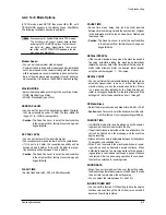
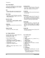
In TECH mode, press SETUP, then press or until
‘MAINTENANCE’ appears in the display. Press Start/Enter.
The following technical options are available
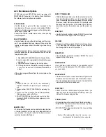
CLEAN DRUM
• Use this feature to get rid of the toner remained in the
development unit, so you can get a clean printout.Perform
this feature if stains or specks appear on the printing mate-
rials and print quality falls.
• Perform this feature several times until a clean printing
material appears.
ADJUST SHADING
• Use this feature to correct the white reference of the scan-
ner if you experience bad copy images. When using this
feature, a white paper should be used to get clean copy
images.
• Use this adjustment feature to achieve best image (scan)
quality depending on the characteristics of the CIS (Contact
Image Sensor) parts.
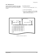
1. Select [ADJUST SHADING] from the Service Mode.
2. Insert a clean white original [Letter Size] into the paper
loading part.
3. Original is scanned if pressing the Setting button.
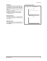
4. If the original scan is completed, message is displayed
on the LCD window and CIS SHADING PROFILE is
output.
• If the output image is different from the normal screen, the
CIS is poor.
Caution:
1.
Always perform the CIS TEST after downloading
Firmware. Otherwise, the system may not operate prop-
erly.
2. Always perform ADJUST SHADING after replacing the
CIS.
3. Always use a clean white paper in ADJUST SHADING
(Maximum paper width: Letter Size).
4. ADJUST SHADING may be performed even in the User
Mode but ADJUST SHADING profile is output only in the
TECH MODE.
REMOTE TEST
• The Remote Test feature can be enabled in order to allow
a remote location to call up and run a diagnostic test on
your machine. You may be instructed by a service repre-
sentative to enable this feature.
NOTIFY TONER LOW
• With this feature enabled, when the toner becomes low, the
toner low information will be sent to ta specified contact
point, for example, the service company. After you access
this menu, select ON, and when the LCD prompts, enter
the name and the number of the contact point, the cus-
tomer's fax number, the model name, and the serial num-
ber.
ROM TEST
• Use this feature to test the machine'S ROM. The result and
the software version appear in the LCD display.
CIS TEST
• This test checks the operation of the Contact Image Sensor
(CIS). Each time the number changes by one increment,
the average ADC value of CIS prints out.
DRAM TEST
• Use this feature to test the machine's DRAM. The result
appears in the LCD display.
SWITCH TEST
Use this feature to test all keys on the operation control
panel. The result is displayed on the LCD window each time
you press a key.
MODEM TEST
• Use this feature to hear various transmission signals to the
telephone line from the modem and to check the modem.
• If no transmission signal sound is heard, it means that the
modem part of the main board is poor.
DTMF TEST
• DTMF (Dual Tone Multi Frequency) signal. When you
press any key on the number keypad including • and #, you
will hear the corresponding key tone.
TONER COUNT
•This feature shows the current state of the toner cartridge.
•TONER CNT: The total number of the dots used to print up
to current time.
•CRU STATE: The page number which the toner cartridge
can print.
• Caution : After replacing Main board to new one, you
should update the information to the new board.
4-2-3 Maintenance Options
Содержание SF-530 Series
Страница 87: ...Electronics ...
Страница 128: ...4 2 SCHEMATIC DIAGRAMS Samsung Electronics Repair Manual 4 2 Main Circuit Diagram 2 6 APOLLO2 MAIN ...
Страница 129: ...4 3 Samsung Electronics SCHEMATIC DIAGRAMS Repair Manual 4 3 Main Circuit Diagram 3 6 APOLLO2 MAIN ...
Страница 130: ...4 4 SCHEMATIC DIAGRAMS Samsung Electronics Repair Manual 4 4 Main Circuit Diagram 4 6 APOLLO2 MAIN ...
Страница 131: ...4 5 Samsung Electronics SCHEMATIC DIAGRAMS Repair Manual 4 5 Main Circuit Diagram 5 6 APOLLO2 MAIN ...
Страница 132: ...4 6 SCHEMATIC DIAGRAMS Samsung Electronics Repair Manual 4 6 Main Circuit Diagram 6 6 APOLLO2 MAIN ...
Страница 133: ...4 7 Samsung Electronics SCHEMATIC DIAGRAMS Repair Manual 4 7 LIU Circuit Diagram 1 2 APOLLO2 LIU ...
Страница 134: ...4 8 SCHEMATIC DIAGRAMS Samsung Electronics Repair Manual 4 8 LIU Circuit Diagram 2 2 APOLLO2 LIU ...
Страница 136: ...4 10 SCHEMATIC DIAGRAMS Samsung Electronics Repair Manual 4 10 Scan Circuit Diagram 200DPI APOLLO2 200DPI ...
Страница 137: ...4 11 Samsung Electronics SCHEMATIC DIAGRAMS Repair Manual 4 11 Scan Circuit Diagram 300DPI APOLLO2 300DPI ...

