


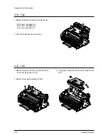

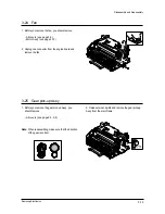
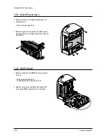
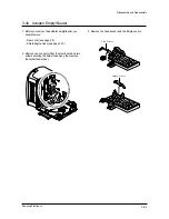
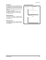
3-22 Holder-Pad
1. Before you remove the holder-pad, you should
remove:
– All covers (see page 3-3, 3-9)
– LSU (see page 3-10)
– Plate upper (see page 3-12)
– Knock-up Ass’y (see 3-13)
– Cap-Pad (see 3-13)
2. Remove the holder-pad from the main frame.
3-14
Samsung Electronics
Disassembly and Reassembly
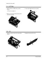
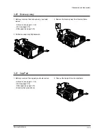
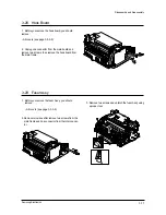
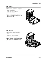
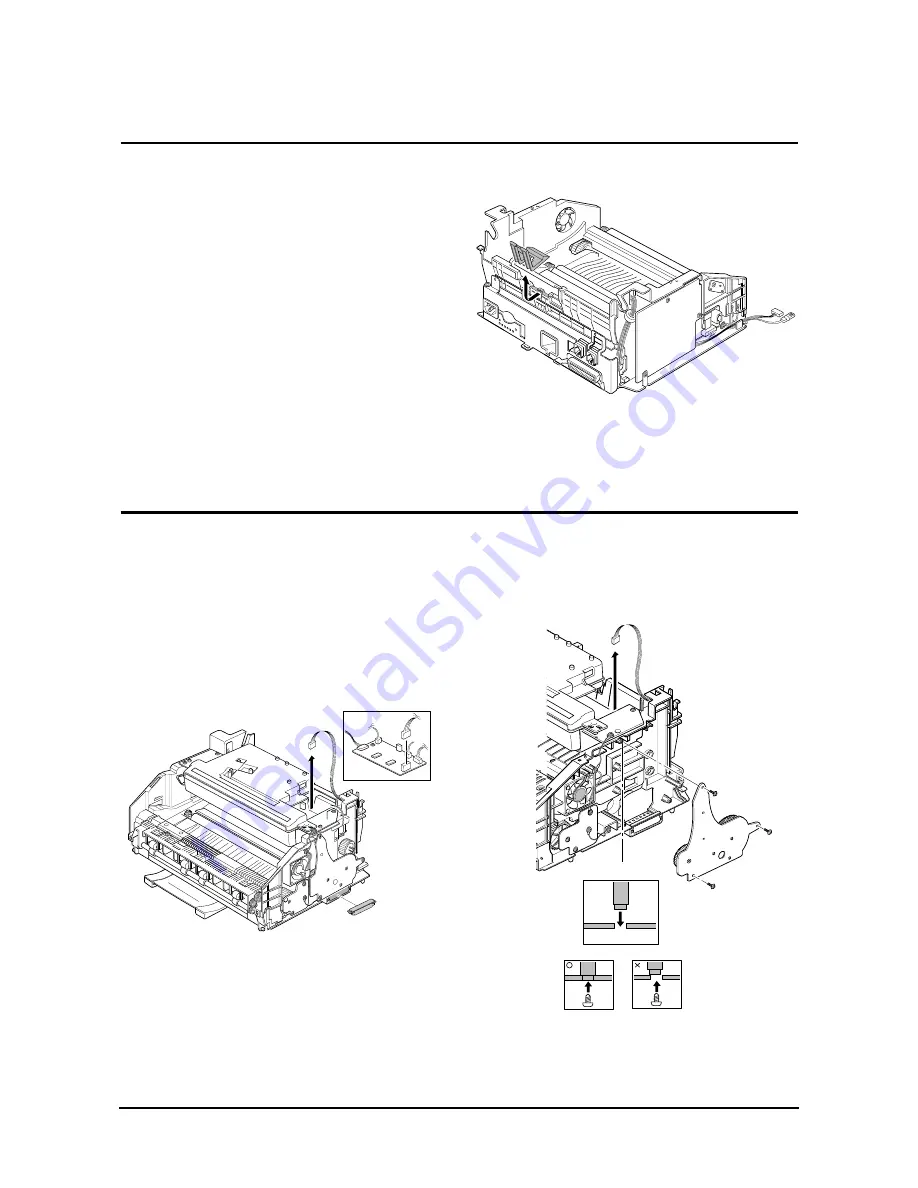
3-23 Motor Ass’y
1. Before you remove the motor Ass’y, you should
remove:
– All covers (see page 3-3, 3-9)
2. Remove four screws securing the motor Ass’y and
unplug one connector from the engine board, then
remove the motor Ass’y.
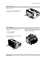
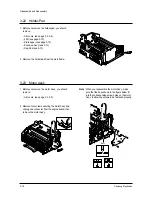
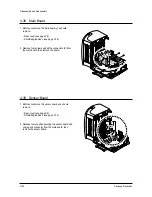
Note : When you reassemble the motor Ass’y, make
sure that the boss shown in the figure below fit
into the corresponding screw holes on the motor
Ass’y to allow the screws to be fastened properly.
Boss
Содержание SF-530 Series
Страница 87: ...Electronics ...
Страница 128: ...4 2 SCHEMATIC DIAGRAMS Samsung Electronics Repair Manual 4 2 Main Circuit Diagram 2 6 APOLLO2 MAIN ...
Страница 129: ...4 3 Samsung Electronics SCHEMATIC DIAGRAMS Repair Manual 4 3 Main Circuit Diagram 3 6 APOLLO2 MAIN ...
Страница 130: ...4 4 SCHEMATIC DIAGRAMS Samsung Electronics Repair Manual 4 4 Main Circuit Diagram 4 6 APOLLO2 MAIN ...
Страница 131: ...4 5 Samsung Electronics SCHEMATIC DIAGRAMS Repair Manual 4 5 Main Circuit Diagram 5 6 APOLLO2 MAIN ...
Страница 132: ...4 6 SCHEMATIC DIAGRAMS Samsung Electronics Repair Manual 4 6 Main Circuit Diagram 6 6 APOLLO2 MAIN ...
Страница 133: ...4 7 Samsung Electronics SCHEMATIC DIAGRAMS Repair Manual 4 7 LIU Circuit Diagram 1 2 APOLLO2 LIU ...
Страница 134: ...4 8 SCHEMATIC DIAGRAMS Samsung Electronics Repair Manual 4 8 LIU Circuit Diagram 2 2 APOLLO2 LIU ...
Страница 136: ...4 10 SCHEMATIC DIAGRAMS Samsung Electronics Repair Manual 4 10 Scan Circuit Diagram 200DPI APOLLO2 200DPI ...
Страница 137: ...4 11 Samsung Electronics SCHEMATIC DIAGRAMS Repair Manual 4 11 Scan Circuit Diagram 300DPI APOLLO2 300DPI ...