CIRCUIT DESCRIPTION
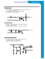
3. Ring detector circuit
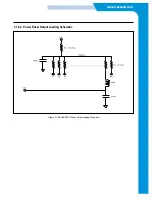
• C9 use for DC coupling and Ring impedance ( Ring impedance spec : Min 4Kohm)
• R1 ( 1/ 1W )protect overvoltage into PC814.
• Ring signal transfer from 1st circuit to 2nd circuit through PC814
• R2/C1 translator to recognize for ring signal.
4. Ext hook detector circuit
• SF-330/331P model have Ext-phone jack to connect TAM or external phone.
• VAR1 protect overvoltage into PC814.
• R7 is marching component of Ext phone for detect another normal phone.
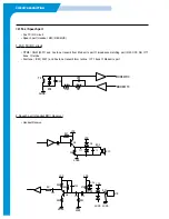
5. DCR / Current limit circuit / impedance
• DCR / Current limit circuit consist of R25, C13, Q2, Q3, R21, R23, R14.
• Current limit circuit apply only EU nation.( Q3, R21 )
• Impedance circuit consist of T2, C26, R43, R41, C35.
R7
R25
C13
Q3
R21
Q2
R23
R14
C26
AGND
R43
C15
R41
C35
C39
T2
100-1016
Содержание SF-335T
Страница 2: ......
Страница 19: ...CIRCUIT DESCRIPTION 2 Chorus 2 Assigned GPO Ports for RHINE ...
Страница 20: ...CIRCUIT DESCRIPTION 3 Chorus 2 Assigned GPI Ports for RHINE 4 Chorus 2 Assigned GPIO Ports for RHINE ...
Страница 21: ...CIRCUIT DESCRIPTION 5 HP IMPORTANT ASIC Ports for RHINE ...
Страница 24: ...CIRCUIT DESCRIPTION 3 1 5 3 Block Diagram Figure 16 Block Diagram of IP_TOP ...
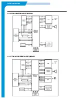
Страница 35: ...CIRCUIT DESCRIPTION 3 1 8 6 FM214 MODEM BLOCK DIAGRAM 3 1 8 7 FM214 VS MODEM BLOCK DIAGRAM ...
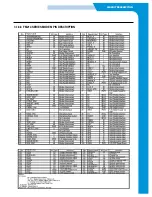
Страница 36: ...CIRCUIT DESCRIPTION 3 1 8 8 FM214 SERIES MODEM PIN DESCRIPTION ...
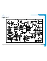
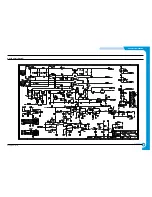
Страница 48: ...4 5 Samsung Electronics SCHEMATIC DIAGRAMS Repair Manual 4 2 LIU Circuit Diagram 2002 06 25 ...

