CIRCUIT DESCRIPTION
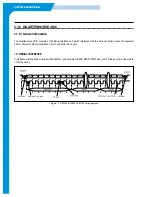
2. HEAD DATA OUTPUT FORMAT
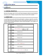
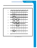
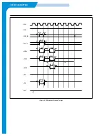
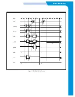
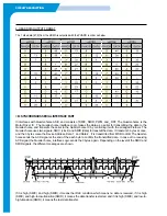
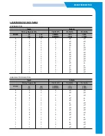
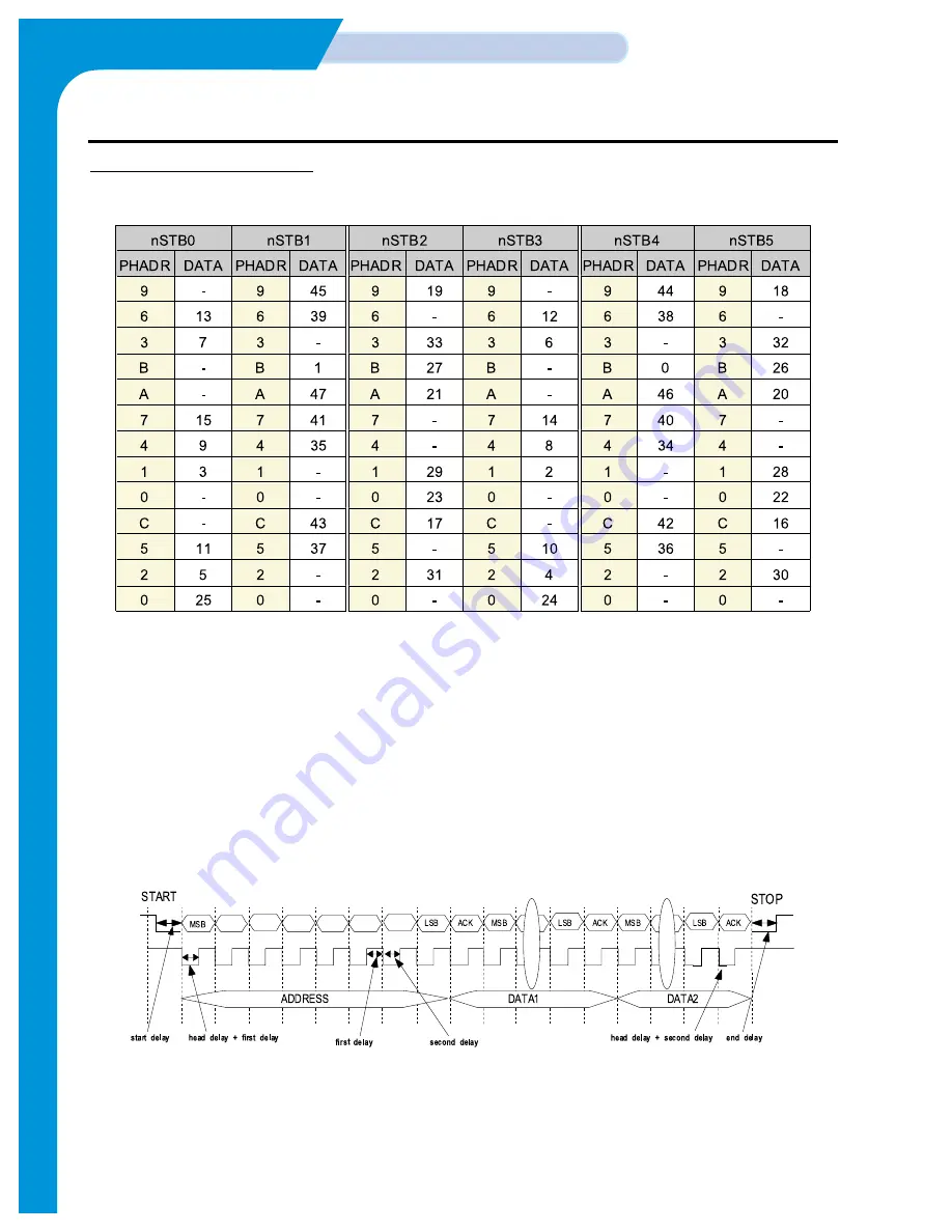
The 1 slice data [47:0] from the HDMA is outputted with the PHADR in order as below.
<9> SYNCHRONOUS SERIAL INTERFACE PART
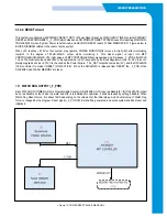
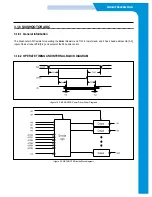
It interfaces with Quarter-horse ASIC and consists of SMIC, SMID, PWM, and _RST. The Quarter-horse is the
Motor Driver IC. The Quarter-horse interface Logic makes the data as a serial for transmitting the data to the
Quarter-horse, and transmits the serial to the Quarter-horse IC by controlling it with the arranged Protocol. The
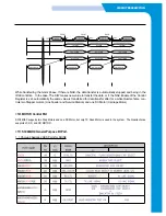
Quarter-horse uses two signals, SMIC (clock) and SMID (data) to transmit the data. It transmits 3 bytes at once,
and the 3 bytes mean the Device Address, Data 1, and Data 2. It is transmitted from MSB to LSB. The Quarter-
horse sends the ACK signal at the end of the each byte to confirm the transmitted data. In case of no receiving
ACK signal, the Quarter-horse_interface Logic sends the 3 bytes again. Depending on the level of the SMIC and
SMID signals, the different messages are shown.
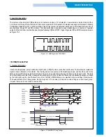
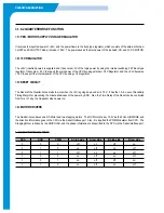
If it is high (SMIC) and high (SMID), it means the IDLE condition which means no data is received, if it is high
(SMIC) and high-to-low-transition (SMID), it means the data transfer is started, and if it is high (SMIC) and low-to-
high-transition (SMID), it means the last data transfer.
Содержание SF-335T
Страница 2: ......
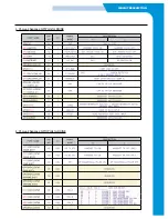
Страница 19: ...CIRCUIT DESCRIPTION 2 Chorus 2 Assigned GPO Ports for RHINE ...
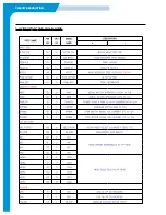
Страница 20: ...CIRCUIT DESCRIPTION 3 Chorus 2 Assigned GPI Ports for RHINE 4 Chorus 2 Assigned GPIO Ports for RHINE ...
Страница 21: ...CIRCUIT DESCRIPTION 5 HP IMPORTANT ASIC Ports for RHINE ...
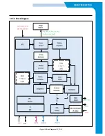
Страница 24: ...CIRCUIT DESCRIPTION 3 1 5 3 Block Diagram Figure 16 Block Diagram of IP_TOP ...
Страница 35: ...CIRCUIT DESCRIPTION 3 1 8 6 FM214 MODEM BLOCK DIAGRAM 3 1 8 7 FM214 VS MODEM BLOCK DIAGRAM ...
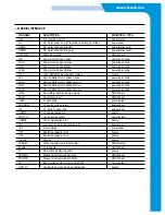
Страница 36: ...CIRCUIT DESCRIPTION 3 1 8 8 FM214 SERIES MODEM PIN DESCRIPTION ...
Страница 48: ...4 5 Samsung Electronics SCHEMATIC DIAGRAMS Repair Manual 4 2 LIU Circuit Diagram 2002 06 25 ...


