CIRCUIT DESCRIPTION
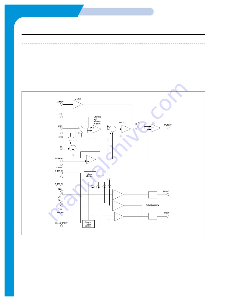
3.1.7 ERTE ASIC
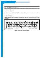
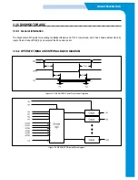
3.1.7.1 General Information
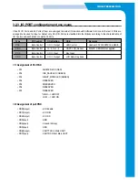
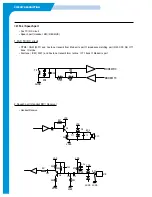
The ERTE ASIC is driven by 19.2V, and consists of three functional blocks, such as the Head, the Pen ID which find out the
kind of head by checking temperature and resistance difference when firing, and the Resistor Test which checks the possibili-
ty of the head firing.
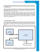
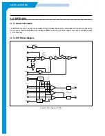
3.1.7.2 ERTE Block Diagram
<Figure 22. Block Diagram of ERTE>
Содержание SF-335T
Страница 2: ......
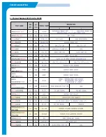
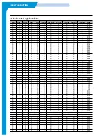
Страница 19: ...CIRCUIT DESCRIPTION 2 Chorus 2 Assigned GPO Ports for RHINE ...
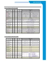
Страница 20: ...CIRCUIT DESCRIPTION 3 Chorus 2 Assigned GPI Ports for RHINE 4 Chorus 2 Assigned GPIO Ports for RHINE ...
Страница 21: ...CIRCUIT DESCRIPTION 5 HP IMPORTANT ASIC Ports for RHINE ...
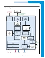
Страница 24: ...CIRCUIT DESCRIPTION 3 1 5 3 Block Diagram Figure 16 Block Diagram of IP_TOP ...
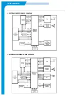
Страница 35: ...CIRCUIT DESCRIPTION 3 1 8 6 FM214 MODEM BLOCK DIAGRAM 3 1 8 7 FM214 VS MODEM BLOCK DIAGRAM ...
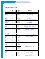
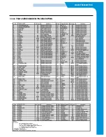
Страница 36: ...CIRCUIT DESCRIPTION 3 1 8 8 FM214 SERIES MODEM PIN DESCRIPTION ...
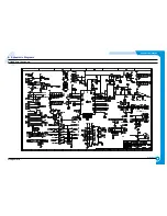
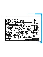
Страница 48: ...4 5 Samsung Electronics SCHEMATIC DIAGRAMS Repair Manual 4 2 LIU Circuit Diagram 2002 06 25 ...

