background image

COLOR CCD CAMERA

User’s Manual

10

COLOR CCD CAMERA

User’s Manual

11

Component 

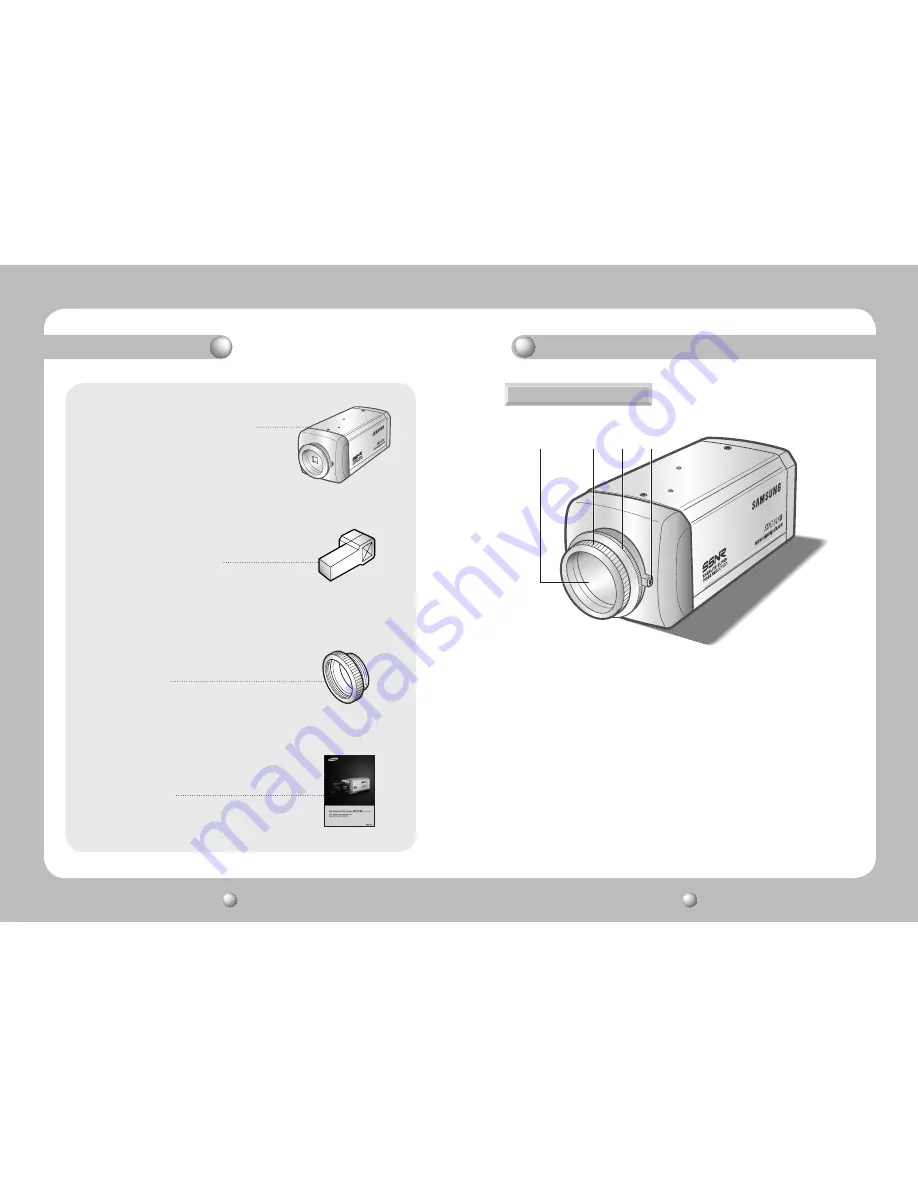
Names and Functions of Parts

FRONT

1. HIGH RESOLUTION COLOR CAMERA

A


CCD protection cap 

Please cover the CCD SENSOR when not using it.

2


C-Mount lens adaptor 

Please install this adapter when using a C-Mount Lens.

3


CS-Mount lens adaptor 

Please remove the C-MOUNT lens adaptor and then attach it. 

4


Back Focus clamp screw


Please loosen the clamp screw with a screwdriver before adjusting the Back Focal 
length.

2. Auto iris lens connection plug

3. C-Mount adaptor

4. Instruction manual

A


2


3


4


Содержание SDC-313B

Страница 1: ...Before installing and operating this product please read this manual thoroughly ENGLISH High Resolution Color Camera SDC 313B User Guide ...

Страница 2: ...ment has been tested and found to comply with limits for a Class A digital device pursuant to part 15 of the FCC Rules These limits are designed to provide reasonable protection against harmful interference when the equipment is operated in a commercial environment This equipment generates uses and can radiate radio frequency energy and if not installed and used in accordance with the instruction ...

Страница 3: ...ach Parts Lens Connecting to Monitor Connecting to Power 15 15 Installation 18 19 Menu Settings LENS selection SHUTTER condition and speed control WHITE BALANCE control BACKLIGHT Backlight Compensation AGC Auto Gain Control SSNR Samsung Super Noise Reduction SENS UP Low illuminance SPECIAL EXIT 20 21 20 24 23 25 26 27 28 29 30 35 Camera Operation 38 Specification 36 Troubleshooting ...

Страница 4: ...ction The PRIVACY function conceals the areas you do not wish to appear on the screen VIDEO DC Drive Lens The video drive lens and the DC drive lens can be selected by the touch of a switch High Sensitivity The built in high sensitivity COLOR CCD enables a clear image even in 0 002 Lux Sens Up illumination Controlled by OSD Menu The camera can be controlled by selecting text displayed on the monit...

Страница 5: ...t important component of the camera Be careful not to smear it with fingerprints Do not drop the camera or subject it to physical shock May cause a product malfunction Never point the camera directly at a strong light May damage the CCD Do not expose the camera to radioactivity Radioactivity exposure may damage the CCD Do not expose the camera to rain or other types of liquids Wipe dry any liquids...

Страница 6: ...e CCD SENSOR when not using it 2 C Mount lens adaptor Please install this adapter when using a C Mount Lens 3 CS Mount lens adaptor Please remove the C MOUNT lens adaptor and then attach it 4 Back Focus clamp screw Please loosen the clamp screw with a screwdriver before adjusting the Back Focal length 2 Auto iris lens connection plug 3 C Mount adaptor 4 Instruction manual A 2 3 4 ...

Страница 7: ...era onto theTripod Mounting Plate TheTripod Mounting Plate can be separated and attached to the top of the camera In this instance please do not tighten the screw to a depth of more than 4mm otherwise serious damage can occur to the inside of the camera 6 This camera package does not include the Tripod Mounting Plate Please refer to the user s manual for installation of the Tripod Mounting Plate N...

Страница 8: ... menu screen LEFT RIGHT buttons Used when changing item values by moving the cursor to the left or right on the menu screen Power lamp Lights up when the correct power is supplied to the camera Installation Lens Lenses are sold separately Lenses such as an auto iris lens CS Mount lens and C Mount lens can be used Keep the lens surface clean if it becomes contaminated with dirt or fingerprints the ...

Страница 9: ...p and attach the C Mount lens to the camera by screwing it in clockwise 1 Please take off the CCD protection cap and C mount adaptor 2 Please attach the CS Mount lens to the camera by screwing it in clockwise When using a C Mount lens When using a CS Mount lens C mount adaptor C mount adaptor C mount adaptor CCD protection cap Please use the specified lens connection parts as shown in the picture ...

Страница 10: ...e of copper wire is at 20 68 The recommended adaptor specification for SDC 313BNA isAC 24V 300mA The recommended adaptor specification for SDC 313BPD is DC 12V 500mA AC PowerType AC 24V 300mA DC PowerType DC 12V 500mA The Recommended adaptor specification for SDC 313BP isAC 24V 300mA or DC 12V 500mA Dual PowerType AC 24V DC 12V Use AC230V 50Hz power source for SDC 313BPH HighVoltageType AC230V 50H...

Страница 11: ... position the arrow to point to the function you wish to operate LEFT button UP button SETUP button RIGHT button DOWN button SETUP LENS DC SHUTTER WHITE BAL ATW BACKLIGHT OFF AGC MIDDLE SSNR LOW SENS UP OFF SPECIAL EXIT Camera Operation SETUP menu LENS selection MANUAL DC VIDEO SHUTTER condition and speed control ESC MANUAL FLK WHITE BALANCE control ATW AWC MANUAL BACKLIGHT Backlight compensation ...

Страница 12: ...UP and DOWN buttons 2 Please select the type of the lens you wish to use by pressing the LEFT or RIGHT button 3 Please press the SETUP button if you wish to return to the previous menu DC VIDEO Auto iris lens selection MANUAL Manual lens selection When using an auto iris lens the setting of the auto iris lens selection switch located on the back of the camera must be on DC or VIDEO depending on th...

Страница 13: ...ues while monitoring the color changes on the object SHUTTER condition and speed control 1 When the SETUP menu is on the screen please position the arrow to point to SHUTTER by using the DOWN button 2 Please select the shutter mode by pressing the LEFT or RIGHT button FLK Please select FLK mode when flickering occurs on the screen due to an imbalance between illumination and frequency NTSC Model 1...

Страница 14: ...on does not operate BACKLIGHT ON BACKLIGHT OFF AGC Auto Gain Control 1 Please position the arrow to point to AGC on the SETUP menu by using the UP and DOWN buttons 2 Please select the mode you wish to operate by pressing the LEFT or RIGHT button As the level of gain increases the screen gets brighter and the level of noise also increases HIGH The gain increases or decreases within the range of 6dB...

Страница 15: ...TER is in the manual mode SENS UP does not operate Notes SENS UP helps maintain a bright clear screen image by automatically detecting changes in the level of light in low light level conditions 1 Please position the arrow to point to SENS UP on the SETUP menu by using the UP and DOWN buttons 2 Please select the mode you wish to operate by pressing the LEFT or RIGHT button AUTO Low light level aut...

Страница 16: ...e level of SHARPNESS increases If the level goes up excessively however it may affect the video image and generate noise Please press the SETUP button IMAGEADJ 1 When the SPECIAL menu screen is displayed select IMAGEADJ by Using the Up and Down buttons so that the arrow indicates IMAGEADJ 2 Select a desired mode using the Up and Down buttons MIRROR ON MIRROR OFF CAMERA ID If the ID is input the ca...

Страница 17: ...ly If the wrong name has been input If you press the SETUP button after moving the cursor to CLR all the letters will be erased If you want to correct a letter please move the cursor to the arrow at the bottom left of the screen and press SET Please position the cursor above the letter you wish to correct and then move the cursor onto the letter you wish to choose and press the SETUP button Notes ...

Страница 18: ...ton OFF MOTION DETECTION mode is cancelled ON Any motion in the selected areas is observed Please select the area you wish to observe from the 4 areas inAREA SEL mode Please select ON mode for the chosen area Please adjust the size of the area to be observed by using the UP DOWN LEFT or RIGHT button Please press the SETUP button to save the changes and complete the setting There is no MD output si...

Страница 19: ... check if an auto iris lens is being used and adjust the brightness level There is a problem with the camera operation The camera surface is too hot and black stripes appear on the screen Please check if an appropriate power source to the camera complies with the manufacturer s standard requirement or if the voltage keeps changing Problem Solution The MOTION DETECTION function is not working Pleas...

Страница 20: ...electable limit x2 x128 O S D Built in English Portuguese Motion Detection ON OFF 4 Programmable Zone SSNR LOW MIDDLE HIGH OFF Selectable Noise Reduction MIRROR ON OFF Privacy Function ON OFF 4 Programmable Zone Sharpness ON OFF LevelAdjustable IRIS Control DC VIDEO Dimension 58 W x 52 H x 121 D mm Operating Temperature Humidity 10 50 30 80 RH Weight 340g 510g 310g 310g DECLARATION OF CONFORMITY A...

Страница 21: ...TEL 82 31 740 8151 8 FAX 82 31 740 8145 SAMSUNG TECHWIN EUROPE CO LTD Samsung House 1000 Hillswood Drive Hillswood Business Park Chertsey Surrey UNITED KINGDOM KT16 OPS TEL 44 1932 45 5300 FAX 44 1932 45 5325 SAMSUNG TECHWIN AMERICA Inc 1480 Charles Willard St Carson CA 90746 UNITED STATES Tol Free 1 877 213 1222 FAX 1 310 632 2195 www samsungcctvusa com SALES NETWORK ...

Отзывы: