3-7 Arm Pinch Roller and Arm Review
Samsung Electronics
3-7
Disassembly and Reassembly
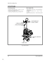
Fig. 3-7 Arm Pinch Roller and Arm Review
1
ARM REVIEW ASS'Y
2
ARM PINCH ROLLER ASS'Y
7
GUIDE PIN
3
SUB DECK HOLE
4
BUSH
5
BUSH
B
C
1
ARM
REVIEW
ASS'Y
2
ARM PINCH
ROLLER ASS'Y
Fig . A
Fig . B
3-7-1 Disassembly
1. Turn the Arm Review Ass’y
1
in the direction of
arrow “B” and lift it to remove. (Fig. A)
2. Lift the Spring Arm Review Ass’y
1
from the
Sub Deck Hole
3
.
3. Push the Arm Pinch Roller Ass’y
2
(arrow “C”)
and lift it to remove.
3-7-2 Reassembly
1. Insert the Arm Pinch Roller Ass’y
2
into the
Bush
4
and then push it in the reverse direction
of arrow “C”.
2. Insert the Arm Review Ass’y
1
into the Bush
5
and push it (reverse of arrow “B”).
Note :
When disassembling or assembling,
do not deform the parts.
Do not stain the roller or poles.
Содержание SC-L710
Страница 61: ...Samsung Electronics 4 44 Alignment and Adjustment MEMO MEMO ...
Страница 63: ...Samsung Electronics 5 2 Exploded View and Parts List 5 1 Mechanical Parts 1 600 ...
Страница 65: ...Samsung Electronics 5 4 Exploded View and Parts List 5 2 Mechanical Parts 2 ...
Страница 67: ...Samsung Electronics 5 6 Exploded View and Parts List 5 3 Mechanical Parts 3 601 ...
Страница 69: ...Samsung Electronics 5 8 Exploded View and Parts List 5 4 Ass y EVF 262 269 904 271 300 ...
Страница 71: ...Samsung Electronics 5 10 Exploded View and Parts List 5 5 Ass y Right ...
Страница 73: ...Samsung Electronics 5 12 Exploded View and Parts List 5 6 Ass y LCD ...
Страница 75: ...Samsung Electronics 5 14 Exploded View and Parts List 5 7 Ass y Left ...
Страница 77: ...Samsung Electronics 5 16 Exploded View and Parts List 5 9 Ass y Front ...
Страница 79: ...Samsung Electronics 5 18 Exploded View and Parts List 5 10 Ass y Camera Deck 116 115 ...
Страница 83: ...Samsung Electronics 5 22 Exploded View and Parts List MEMO MEMO ...
Страница 99: ...7 2 Samsung Electronics PCB Diagrams 7 1 Main PCB Component Side ...
Страница 100: ...7 3 Samsung Electronics PCB Diagrams ...
Страница 101: ...7 4 Samsung Electronics PCB Diagrams 7 2 Main PCB Conductor Side ...
Страница 102: ...7 5 Samsung Electronics PCB Diagrams ...
Страница 103: ...7 6 Samsung Electronics PCB Diagrams 7 3 Rear PCB Component Side Conductor Side ...
Страница 104: ...7 7 Samsung Electronics PCB Diagrams 7 4 EVF PCB Component Side Conductor Side ...
Страница 105: ...7 8 Samsung Electronics PCB Diagrams 7 5 Function PCB 7 6 Front PCB 7 7 LCD PCB ...
Страница 106: ...7 9 Samsung Electronics PCB Diagrams 7 8 CCD PCB Component Side Conductor Side ...
Страница 107: ...7 10 Samsung Electronics PCB Diagrams 7 9 USB PCB Component Side Conductor Side ...
Страница 108: ...8 1 Samsung Electronics 8 Wiring Diagram ...
Страница 109: ...8 2 Samsung Electronics Wiring Diagram MEMO MEMO ...
Страница 111: ...9 2 Samsung Electronics Schematic Diagrams 9 1 DC DC Converter Main ...
Страница 112: ...9 3 Samsung Electronics Schematic Diagrams 9 2 System Control Main ...
Страница 113: ...9 4 Samsung Electronics Schematic Diagrams 9 3 Audio Main ...
Страница 114: ...9 5 Samsung Electronics Schematic Diagrams 9 4 Pre Amp Main ...
Страница 115: ...9 6 Samsung Electronics Schematic Diagrams 9 5 Front ...
Страница 116: ...9 7 Samsung Electronics Schematic Diagrams 9 6 Function ...
Страница 117: ...9 8 Samsung Electronics Schematic Diagrams 9 7 EVF ...
Страница 118: ...9 9 Samsung Electronics Schematic Diagrams 9 8 LCD ...
Страница 119: ...9 10 Samsung Electronics Schematic Diagrams 9 9 CCD ...
Страница 120: ...9 11 Samsung Electronics Schematic Diagrams 9 10 CAMERA Main ...
Страница 152: ...Samsung Electronics 1 30 Operation MEMO MEMO ...


