44
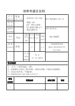
Self-diagnostics check list
TROUBLESHOOTING
LED
R-1-
R-1-
R-1-
R-1-
R-1-
R-1-
F-1-
F-1-
F-1-
F-1-
F-1-
F-1-
R-10-
R-10-
F-10-
F-10-
Item
Ice Maker Sensor Error
R-Sensor Error
R-DEF-Sensor Error
R-FAN Error
Ice Maker Error
R-DEF. Error
Ambient-Sensor Error
F-Sensor Error
DEF-Sensor Error
F-FAN Error
C-FAN Error
F-DEF. Error
Pantry-Damper-Heater Error
Pantry-Sensor Error
Panel Main communication Error
Load Main communication Error
Trouble contents
Diagnostic method
Display error : separation of sensor housing
part, contact error, disconnection, short
circuit
Display error of detecting temperature of
sensor: more than 149
(+65°C) or less
than -58 (-50°C)
Display error : sensor housing separation,
contact error, disconnection, short circuit
Display error by detecting temperature of
sensor: more than 149 (+65°C) or less
than -58 (-50°C)
Display "oP/LC-Er" in the panel with alarm :
MICOM MAIN
LOAD communication error
MICOM MAIN
PANEL communication error
LC-Er is displayed when the Option is not
equivalent with the right value
Actually, it is desirable to recheck the condition with
the oscilloscope after replacing Main and Panel
PCB.
When checking the voltage of MAIN PCB CN90
#3 CN90#4 : shall be between 4.5V~1.0V.
When checking the voltage of MAIN PCB
CN30#6 CN75#1:shall be between 4.5V~1.0V
When checking the voltage of MAIN PCB
CN30#7 CN75#:shall be between 4.5V~1.0V
Voltage of MAIN PCB CN75 Orange
Gray
shall be between 7V~12V
After replacing ice maker, check the operation
by turning the appliance ON again.
When checking the voltage of MAIN PCB
CN32#1 #4 : shall be between 4.5V~1.0V.
When checking the voltage of MAIN PCB
CN30#3 CN75#1:shall be between 4.5V~1.0V
When check the voltage of MAIN PCB
CN30#4 CN75#1:shall be between 4.5V~1.0V
Voltage of MAIN PCB CN75 Yellow
Gray
shall be between 7V~12V.
Voltage of MAIN PCB CN75 Sky-blue
Gray
shall be between 7V~12V.
When checking the voltage of MAIN PCB
CN30#8
#9 : shall be between 4.5V~1.0V.
Display error : separation of fresh food compartment defrost heater housing
part, contact error, disconnection, short circuit or temperature fuse error.
Display error : the defrosting does not finish though fresh food compartment
defrost is heating continuously for more than 80 minutes.
After separating MAIN PCB CN70,CN71 from PCB, check the
resistance value between CN70 White CN71 Orange shall be
102(441) ohm 7%. (Resistant value is varied by the input power)
Check 0 Ohm : heater short, Ohm : wire / bimetal Open.
After separating MAIN PCB CN70,CN71 from PCB, check the
resistant value between CN70 brown
CN71 Orange shall be
102(220) ohm
7%. (Resistant value is varied by input power)
Check 0 Ohm : heater short,
Ohm : wire / bimetal Open.
After separating MAIN PCB CN91from PCB, check the resistant
value between Black
brown wire shall be 145 ohm
7%.
Check 0 Ohm : heater short,
Ohm : wire / bimetal Open.
Display error : separation of freezer compartment defrost heater housing
part , contact error, disconnection, short circuit or temperature fuse error.
Display error : the defrosting does not finish though fresh food compartment
compartment defrost is heating continuously for more than 70 minutes.
Display error during operation of applicable
fan motor : Feed Back signal line contact
error, separation of motor wire, motor error
Display error : ice making kit is harvested
more than 3 times and level error
** Apply to the applicable Ice Maker model.
Display error during operation of applicable
fan motor : Feed Back signal line contact
error, motor wire separation, motor error
Display error during operation of applicable
fan motor : Feed Back signal line contact
error, motor wire separation, motor error
Display error when open error is detected by damper
heater : separation of Damper Heater housing part,
contact error, disconnection, short circuit
Display error : separation of sensor housing, contact error,
disconnection, short circuit.
Display error by detecting temperature of sensor: more
than 149 (+65°C) or less than -58 (-50°C)
Содержание RF265AARS RF266AARS RF26NBRS1RF265AABP RF266AABP RF26NBBP1RF265AAWP RF266AAWP RF26NBSH1RF265AASH RF266AASH
Страница 2: ......
Страница 19: ...18 Refrigerator PRODUCT SPECIFICATIONS 2 9 Cooling Air Circulation Freezer ...
Страница 85: ...84 EXPLODED VIEW PARTS LIST 5 4 Disassembly of Freeze Door 10 2 7 2 7 4 7 1 7 3 10 1 10 9 7 2 2 1 3 5 4 6 6 9 ...
Страница 104: ...103 EXPLODED VIEW PARTS LIST 5 4 Disassembly of Freeze Door 10 2 7 2 7 4 7 1 7 3 10 1 10 9 7 2 2 1 3 5 4 6 6 9 ...
Страница 109: ...108 EXPLODED VIEW PARTS LIST 5 6 Disassembly of Refrigerator Door Right 1 2 5 5 6 4 3 6 3 8 2 8 1 6 4 6 1 6 2 7 8 ...
Страница 120: ...119 8 1 Whole block diagram 8 Shematic Diagram AC115V AC115V AC115V 8 1 1 MODEL RF266 BETTER ...
Страница 121: ...120 Shematic Diagram AC115V AC115V AC115V 8 1 2 MODEL RF265 GOOD RF26NB ...
Страница 122: ...121 8 2 CIRCUIT DIAGRAM Shematic Diagram 8 2 1 Sheet 1 of 2 ...
Страница 123: ...122 8 2 CIRCUIT DIAGRAM Shematic Diagram 8 2 2 Sheet 2 of 2 ...


