background image

Service Manual

Reference Information

2-6

Samsung Electronics

2.5  Wireless LAN

• This product can be used with a wireless LAN (Option)

- The wireless LAN function uses radio technology, instead of using LAN cable, to connect to an

access point for printing.

- For a wireless LAN connection in Infrastructure mode an AP is needed, (purchased separately) 
- For a wireless LAN connection in Ad-Hoc mode an appropriate Wireless I/F card is required fitted

to a computer, (purchased separately)

- It is possible to use a wireless LAN connection with wired LAN. 
- If an AP is installed in an office or at home, the wireless LAN function can be simply configured

and used.

• Types of desk top PC (or Lap top) that uses the wireless LAN.

• About the certificated mark of Wi-Fi

TM

- Wi-Fi

TM

is a registered trademark of the WECA (Wireless Ethernet Compatibility

Alliance). Over 50 wireless LAN companies are member of this organisation. Most of
the main wireless networking companies are attending including such companies as
Lucent Technologies, Cisco, Intel/Symbol, 3Com, Enterasys (Cabletron), Compaq,
IBM, Nokia, Dell, Philips, Samsung Electronics, Sony, Intersil, etc.. This mark certifies
mutual compatibility amongst the product of these companies.  Wi-Fi

TM

(IEEE 802.1) is

certified as a standard of the wireless LAN market.

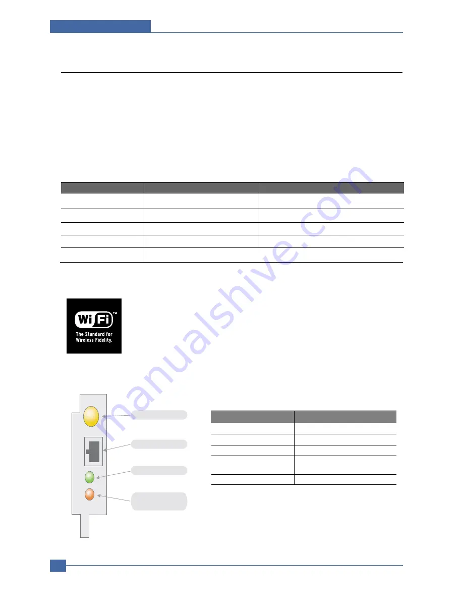
• LED Condition and Status

Division

Basic type

Recommend type

CPU

Over PENTIUM 233M

PENTIUM 300MHz

MEMORY

Over 64MB

Over 128MB

VIDEO CARD

Over 800X600

Over 1024X768

OS

Over WINDOWS 98

Over WINDOWS ME

INTERFACE CARD 

A product has a certificated mark of Wi-Fi

TM

LED Condition

Status

Active LED random blink

Normal NPC &Normal packet receive

Active LED regular blink

Normal NPC &No Packet

Active LED Off/On maintenance NPC Initial inferiority

Link LED On

The link LED On OPC,Normally linked

(Red:Wireless,Green:Wire,Orange:Wire/Wireless)

Link LED Off

Link LED off NPC,Link Inferiority

Antenna connector

RJ-45 Jack

Active LED(Green)

Link LED

(Red/Green/Orange)

[LED STATUS]

Содержание ML-3561N Series

Страница 1: ...cations 4 Summary of product 5 Disassembly and Reassembly 6 Alignment and Adjustments 7 Troubleshooting 8 Exploded Views and Parts List 9 Block Diagram 10 Connection Diagram 11 Schematic Diagram Manual SERVICE DIGITAL LASER PRINT ML 3560 Series ML 3561N XAA Basic Model ML 3560 ...

Страница 2: ...ny human access to laser radiation above a Class I level during normal operation user maintenance or prescribed service condition Warning Never operate or service the printer with the protective cover removed from Laser Scanner assembly The reflected beam although invisible can damage your eyes When using this product these basic safety pre cautions should always be followed to reduce risk of fire...

Страница 3: ... or removing the power connector The power connector must be inserted com pletely otherwise a poor contact could cause overheating possibly leading to a fire When removing the power connector grip it firmly and pull 7 Take care of the power cable Do not allow it to become twisted bent sharply round corners or other wise damaged Do not place objects on top of the power cable If the power cable is d...

Страница 4: ...rry out the following procedures before dismantling the printer or replacing any parts 1 Check the contents of the machine memory and make a note of any user settings These will be erased if the mainboard or network card is replaced 2 Ensure that power is disconnected before servicing or replacing any electrical parts 3 Disconnect printer interface cables and power cables 4 Only use approved spare...

Страница 5: ...do you can get harm 3 When you move the printer This printer weighs 21kg including toner cartridge and cassette Use safe lifting and handling techniques Use the lifting handles located on each side of the machine Back injury could be caused if you do not lift carefully 4 Ensure the printer is installed safely The printer weighs 21Kg ensure the printer is installed on a level surface capable of sup...

Страница 6: ...m to prevent electrostatic charge buildup in the vicinity of the assem bly 3 Use only a grounded tip soldering iron to solder or desolder ESDs 4 Use only an anti static solder removal device Some solder removal devices not classified as anti static can generate electrical charges sufficient to damage ESDs 5 Do not use Freon propelled chemicals When sprayed these can generate electrical charges suf...

Страница 7: ...Samsung Electronics Service Manual Precautions 1 6 ...

Страница 8: ...1 Tool for Troubleshooting The following tools are recommended safe and easy troubleshooting as described in this service manual DVM Digital Volt Meter Standard Indicates more than 3 digits Driver Standard type type M3 long M3 short M2 long M2 short Tweezers Standard For general home use small type Cotton Swab Standard For general home use for medical service Cleaning Equipments Standard An IPA Is...

Страница 9: ...tor CPU Central Processing Unit dB decibel dBA decibel A dBM decibel milliwatt DC direct current DCU Diagnostic Control Unit DPI Dot Per Inch DRAM Dynamic Random Access Memory DVM Digital Voltmeter ECP Enhanced Capability Port EDC Embedded Diagnostic control EEPROM Electronically Erasable Programmable Read Only Memory EMI Electro Magnetic Interference EP electrophotographic EPP Enhanced Parallel P...

Страница 10: ...hy place NVRAM nonvolatile random access memory OPC Organic Photo Conductor OP Operation Panel Equipment PBA Printed Board Assembly PCL Printer Command Language Printer Control Language PDL Page Discription Language PPM Page Per Minute PPS Pulse Per Second PS Post Script PTL Pre Transfer Lamp PWM Pulse Width Modulation Q PID Quick Printer Initiating Device Q ty quantity RAM Random Access Memory RO...

Страница 11: ...ough room to open the printer trays covers and allow for proper ventilation see diagram below Provide the proper environment A firm level surface Away from the direct airflow of air conditioners heaters or ventilators Free of extreme fluctuations of temperature sunlight or humidity Clean dry and free of dust ...

Страница 12: ...he sample patterns shown below are the standard test patterns used in the factory The life of the toner cartridge developer cartridge and printing speed are measured with the pattern shown below 5 The A4 ISO 19752 standard pattern samples are reproduced reduced to 70 of the actual A4 size ...

Страница 13: ...member of this organisation Most of the main wireless networking companies are attending including such companies as Lucent Technologies Cisco Intel Symbol 3Com Enterasys Cabletron Compaq IBM Nokia Dell Philips Samsung Electronics Sony Intersil etc This mark certifies mutual compatibility amongst the product of these companies Wi FiTM IEEE 802 1 is certified as a standard of the wireless LAN marke...

Страница 14: ...h without options Weight Net 17 5 Kg with print cartrige Gross 21 Kg Acoustic Noise Stand by Less than 35 dB Printing Less than 55 dB Sleep mode Background Noise Power save mode Enable Toner save mode Enable Consumable Parts Retard Roller Up to 150 000 Pages Transfer Roller Up to 70 000 Pages Fuser Assembly Up to 80 000 Pages Toner Sensor Yes dot counting Toner Type Non Magnetic toner Toner Initia...

Страница 15: ... Level3 MAC OS 8 6 9 2 10 1 10 3 PCL5e Various Linux OS including Red Hat Caldera Debian Mandrake Slackware SuSE and Turbo Linux Interface Parallel IEEE 1284 Bidirectional Parallel Modes supported Compatible Nibble Byte ECP USB without HUB mode USB 2 0 compliant High Speed Network Interface 10 100 Base TX 802 11bWirelessLAN Interface switching Automatic Interface time out 999 seconds Font 45 Scala...

Страница 16: ...ndex Card 3 x 5 in O A6 Postcard 105 x 148 mm O Envelopes Monarch 3 88 x 7 5 in O 10 Commercial 4 13 x 9 5 in O C5 162 x 229 mm O C6 114 x 162 mm O DL 110 x 220 mm O Transparencies Letter 8 5 x 11 in O X X X A4 210 x 297 mm O X X X Labels Letter 8 5 x 11 in O A4 210 x 297 mm O Custom Width 76 216 mm 3 8 5 in O Length 127 356 mm 5 14 in Tray 1 MPT Weight 60 163 g m 2 16 43 lb Tray 2 and 3 Weight 60...

Страница 17: ...ity Output capacity ITEM DESCRIPTION Cassette Paper 500 sheets 75gr MP tray Paper 100 sheets 75gr Transparencies 50 sheets Envelopes 10 sheets Labels 25 sheets Option Cassette 500sheets 75gr ITEM DESCRIPTION Face Down Top tray 250 sheets Face UP Rear tray 100 sheets ...

Страница 18: ...mmary of Product Service Manual 4 1 Samsung Electronics 4 4 4 Summary of Product This chapter describes the functions and operating principal of the main component 4 1 Printer Components 4 1 1 Front View ...

Страница 19: ...Service Manual Summary of Product 4 2 Samsung Electronics 4 1 2 Rear View ...

Страница 20: ...Summary of Product Service Manual 4 3 Samsung Electronics 4 1 3 Control Panel The control panel on the top right side of your printer has the display and the nine buttons 4 1 3 1 Display ...

Страница 21: ...Service Manual Summary of Product 4 4 Samsung Electronics 4 1 3 2 Overview of Control Panel Menus The control panel menus are used to configure the printer for your environment ...

Страница 22: ...Purpose Tray to the rear output tray Create professional documents You can customize your documents using Watermarks such as Confidential Print Booklets This feature enables you to easily print the pages required to create books Once printed all you have to do is to fold and staple the pages Print Posters The text and pictures of each page of your document are magnified and print ed across the sel...

Страница 23: ...0 ML 3561N ML 3561ND Maximum Print Speed Monochrome 35 35 35 Memory Standard 32 Mbytes 32 Mbytes 64 Mbytes Up to 286 Mbytes Optional PostScript and PCL Fonts Yes Yes Yes Default Resolutions dpi 600 x 600 dpi 600 x 600 dpi 600 x 600 dpi 500 Sheet Feeder Optional Optional Optional Network Interface Optional Standard Standard Automatic 2 Sided Printing Duplex Optional Optional Standard HDD Optional O...

Страница 24: ...Summary of Product Service Manual 4 7 Samsung Electronics 4 2 System Layout Cassette Duplex MPF Print Cartridge LSU Fuser SMPS HV PS Board Duplex Solenoid ...

Страница 25: ...tion and removing electronic static function 4 Retard roller It takes an arrangement method which uses a stopper roller and a weight without electric actuator It has paper separating function driving control function and multi feeding prevention function 6 Registration roller It has a paper arranging function paper transferring function paper detecting function jam remov ing function and so on 7 M...

Страница 26: ... Pressure roller A pressure roller mounted under a heat roller is made of a silicon resin and the surface also is coated with Teflon When a paper passes between a heat roller and a pressure roller toner adheres to the surface of a paper permanently 5 Items for safety Protecting device for overheating 1st protection device Hardware cuts off when overheated 2nd protection device Software cuts off wh...

Страница 27: ...oping Method Non contacting method Toner Non magnetic 1 component pulverized type toner The life span of toner 6 000 or 12 000 pages LSA Pattern A4 standard Toner remaining amount detecting sensor Yes OPC Cleaning Cleaning blade type Management of disusable toner Collect the toner by using Cleaning Blade OPC Drum protecting Shutter Yes Classifying device for toner cartridge ID is classified by int...

Страница 28: ...d The Engine Board and the Controller Board are in one united board 4 3 1 1 Asic SPGP V3 RM1020E I Cache 32KB D Cache 32KB 32 bit RISC embedded processor core Dual bus architecture for bus traffic distribution AMBA High performance Bus AHB System Bus with SDRAM SDRAMC 32 Bits Only 100MHz 5 Banks Up to 128MB per Bank ...

Страница 29: ...ter V ideo Controller without RET Algorithm HPV C Printer V ideo Controller with RET algorithm Line Memory Lookup Table Memory 512 x 8 4096 x 16 Dual Single Beam LV DS Pad V DO HSYNC PCI Controller 32Bits 33 66MHz PCI Local Bus Specification rev 2 2 compliant Host Agent Mode Support 4 Devices in Host Mode NAND Flash Controller 8 16 Bits H W ECC Generation Auto Boot Mode using internal SRAM 4KB Eng...

Страница 30: ...ompresses the PCL font then stores it Capacity 32M byte SDRAM It is used as Swath Buffer System Working MemoryArea etc when printing It stores Font List compressed into Flash memory on DRAM and uses it as PCL font in case of model for export Capacity 32M Byte Basic up to 256Mbyte User Option Type SDRAM 100MHz 133MHz 16bit 4 3 1 3 Others The Option PBA can be mounted for supporting the serial commu...

Страница 31: ...EXECUTION UNIT ROTATOR SCALER HALFTONER 1024X8 256X8 ENGINE CONTROLLER LSU I F PULSE WIDTH MODULATOR MOTOR CONTROLLER 2X2X128X16 ADC DAC MISC BIST CONTROLLER ENGINE COMM I F INTERRUPT CTRL TIME CONTROL UNIT 6CH SYSTEM BUS ARBITER ROM CONTROLLER PCI BRIDGE PCI 2 2 NAND Flash CONTROLLER ARM1020E EXTERNAL DMA CONTROLLER 4CH IO CONTROLLER SFR BUS INTERFACE DECODER SYSTEM BUS INTERFACE ETHERNET UART 5C...

Страница 32: ... Tray2 When Jam at top open top cover message is displayed on the LCD panel the feed sensor should be checked Paper exit sensing The exit sensor detects that Jam at exit error When the paper sticks into the exit part Jam at Exit Open top cover message is displayed on the LCD panel Cover open sensing The cover open switch is on the top frame it dectects whether top cover is open or closed When top ...

Страница 33: ...of Product 4 16 Samsung Electronics 4 3 2 SMPS HVPS board The SMPS supplies DC Power to the System It takes 110V 220V and outputs the 3 3V 5V 24V to supply the power to the main board The HV PS board creates the high voltage ...

Страница 34: ...put Control Signal MHV PWM CPU is HV output when PWM is Low Cleaning Voltage THV The Transfer V oltage is not outputted because the THV PWM is controlled with high The Transfer V oltage is outputted because the THV Enable Signal is controlled with low The output fluctuation range is big because there is no Feedback control Output V oltage 1 0KV 15 when cleaning 200M Developing Voltage DEV DC Input...

Страница 35: ...IN CON 3 CON 3 CON 3 3 3V PIN 9 11 13 5V PIN 15 17 24V PIN 1 3 5 GND PIN 21 GND PIN 19 GND PIN 23 25 27 3 Rated Output 3 3V 5 5V 5 24V 10 15 24V 10 15 3 13 3 47V 4 75 5 25V 21 6 27 6V 21 6 27 6V 4 Max Output Current 2 0A 1 0A 3 8A 0 7A 5 Peak Loading Current 2 5A 1 5A 4 0A 1 0A 6 RIPPLE NOISE V oltage Under 100mV p p Under 150mV p p Under 500mV p p Under 500mV p p 7 Maximum output 6 6W 4 0W 67 2W ...

Страница 36: ...12ohm Com Bi wave 3kV 2ohm Nor Environment Condition Operating temperature range 0 40 Maintaining temperature range 25 85 Preserving Humidity Condition 30 90 RH Operating atmospheric pressure range 1atm 4 3 2 3 Fuser control When the power voltage of the machine is too high or too low Fuser on is stopped to protect the fuser When the AC is not applied to the fuser control circuit the fuser does no...

Страница 37: ...onment or the environment of the set and the voltage value which changes due to the environments is changed throughAD converter The voltage value for impressing to the trans fer roller is decided by the changed value ITEM Description JAM 0 JAM 1 JAM 2 DUPLEX JAM 1 DUPLEX JAM2 After pick up paper cannot be entered due to paper is not fed After pick up paper entered but it cannot reach to the feed s...

Страница 38: ...n the LD and drives the polygon motor When the detector detects the beam Hsync occurs When the polygon motor speed becomes strady Lready occurs If two conditions are satisfied the status are not satisfied the error shown in below occurs Error Description LCD Display Open Heat Error When warming up it has been lower than 60 over 35 seconds Engine Fuser Error Low heat Error Standby Engine Low Heat E...

Страница 39: ...Service Manual Summary of Product 4 22 Samsung Electronics ...

Страница 40: ...machine note the cable routing that will be affected Whenever servicing the machine you must perform as follows 1 Check to verify that documents are not stored in memory 2 Be sure to remove the print cartridge before you disassemble parts 3 Unplug the power cord 4 Use a flat and clean surface 5 Replace only with authorized components 6 Do not force plastic material components 7 Make sure all compo...

Страница 41: ...at both ends of the roller then remove the roller Cautions When Replacing a Transfer Roller Do not grab the Transfer Roller shown in picture A It may cause a malfunction due to a foreign object Hold the both side of the Transfer Roller shown in picture B when replacing it Transfer Roller A B Transfer Roller Holder Open Cover ...

Страница 42: ... Manual 5 3 Samsung Electronics 5 3 MPF Ass y 1 Open the MPF Ass y 2 Remove two springs from the Knock Up Plate Ass y 3 Remove the Tray Link from the MP Cover 4 Push the MP Cover and remove it as shown below Tray Link MPF Ass y MP Cover ...

Страница 43: ... Remove the Photo Interrupter and the MP Actuator as shown below Holder Pad Ass y Friction Pad MP Actuator 5 Remove MP Cover in the direction of arrow as shown below NOTICE Do not separate the spring from the MP Pick Up Rack for convenience of assembling Locate the hook sec tion of the spring that is connected to the Knock Up Plate Ass y as shown in the outside for convenience of assembling Tray L...

Страница 44: ...cs 5 5 Retard Ass y 1 Remove the Roller Ass y as shown below NOTICE When you reassemble the Retard Roller Ass y Make sure that the let and of the Retard Roller fits into the Retard Shaft 2 Releasse the lock as shown below and take out the retard Ass y Retard Ass y ...

Страница 45: ... and Reassembly 5 6 Samsung Electronics 5 6 Feed2 Idle Unit 1 Before you remove the Feed2 Idle Unit you should remove Holder Pad Ass y Refer to the 5 4 2 Remove four screws Then lift the Idle Unit as shown below Feed2 Idle Unit ...

Страница 46: ... Manual 5 7 Samsung Electronics 5 7 Cover Right 1 Pull the Cassette out of the printer 2 Remove the Cover Dummy and Cover Control Box 3 Remove two screws and take out the right side as shown below Cassette Cover Control Box Cover Right ...

Страница 47: ...s as shown below 3 The Connectors are located as shown below 4 Remove two screws and take out the Dummy Bracket 5 Remove six screws and take out the Main PBA Duplex SMPS HVPS PBA PTL Cover Open Thermistor LSU Toner Sensor DEVE Motor DPX_SOL Key Panel HDD Optional Network Card Main Motor Exit Sensor Connector PBA Memory Optional USB Port P1284 Port SCF Key Panel Dummy Bracket Main PBA ...

Страница 48: ...Unplug the two Connectors from the Main Motor Ass y and the Connector PBA 3 Remove the E ring and take out the Clutch 4 Remove six screws and take out the Main Drive Ass y 5 When separating the Main Motor Ass y disconnect the Connector from the Main Motor Ass y remove four screws and then remove the Main Motor Ass y Connector PBA Main Drive Ass y Main Motor Ass y Clutch E Ring ...

Страница 49: ... you should remove Cover Right Refer to the 5 7 2 Unplug the Connector from the DEVE Motor Ass y 3 Remove four screws and take out the DEVE Drive Ass y 4 When separating the DEVE Motor Ass y disconnect the Connector from the DEVE Motor Ass y remove four screws and then remove the DEVE Motor Ass y DEVE Drive Ass y DEVE Motor Ass y ...

Страница 50: ...A 1 Before you remove the Connector PBA you should remove Cover Right Refer to the 5 7 2 Unplug the all Connectors from the Connector PBA and take it out 3 The Connectors are located as shown below Connector PBA Cassette Open S W MP Solenoid Main Solenoid Main Clutch MP Empty Main PBA ...

Страница 51: ...rive Ass y Refer to the 5 9 2 Unplug the MP Solenoid Harness and the Main Solenoid Harness from the Connector PBA 3 Remove one screws and take out the MP Solenoid 4 Remove one screws and take out the Main Solenoid NOTICE It is not necessary to disassemble the Main Drive Ass y to remove the MP Solenoid MP Solenoid Main Solenoid MP Solenoid Main Solenoid Connector PBA ...

Страница 52: ...embly and Reassembly Service Manual 5 13 Samsung Electronics 5 13 Rear Cover 1 Open the Rear Cover and then take out the Stopper 2 Remove the Rear Cover in the direction of arrow 2 1 ie Stopper 2 1 Rear Cover ...

Страница 53: ...e Manual Disassembly and Reassembly 5 14 Samsung Electronics 5 14 Cover Left 1 Pull the Cassette out of the printer 2 Remove two screws and take out the left side 3 Take out the Cover Left Cassette Cover Left ...

Страница 54: ...e Rear Cover Refer to the 5 14 Cover Right Refer to the 5 7 Cover Left Refer to the 5 13 2 Open the MPF Ass y the Rear Cover the Open Cover 3 Unplug the two Connectors after you remove the three screws from the Main PBA 4 Unlatch both ends of the Top Cover 5 Unlatch the hook and take out the Top Cover Open Cover MPF Ass y Key Panel ...

Страница 55: ...x screws and then take out the LCD Panel and the Key Panel LCD Panel Key Panel 5 16 Open Cover 1 Before you remove the Open Cover you should remove Top Cover Refer to the 5 15 2 Remove two screws and take out the Stopper 3 Take out the Open Cover as shown below Stopper Open Cover ...

Страница 56: ...y Service Manual 5 17 Samsung Electronics 5 17 Inner Cover 1 Before you remove the Inner Cover you should remove MPFAss y Refer to the5 3 Top Cover Refer to the 5 15 2 Remove two screws and take out the Inner Cover Inner Cover ...

Страница 57: ...Lever Then take out the Fuser Ass y as shown below 3 Remove two screws and take the Thermostat out of the Fuser Ass y 4 Remove two screws securing the Electrode L R and remove it as shown below 5 Remove two screws securing the Fuser Upper Unit and remove it as shown below Thrmistor Connector Fuser Ass y Thermostat 2 1 Fuser Upper Unit Fuser Lower Unit Electrode Bush Harness L Harness R ...

Страница 58: ...t as shown below 7 Remove two screws and take out the Gear Bracket 8 Take out the Heat Roller Ass y as shown below 9 Remove the screw securing the Thermistor and remove it as shown below Gear Bracket Thermistor Heat Roller Ass y Cover Fuser Upper Fuser Gear Bearing Pressure Roller Cover Fuser Lower Release Lever R Release Lever L ...

Страница 59: ... Exit Solenoid Ass y you should remove Top Cover Refer to the 5 15 2 Unplug the Duplex Solenoid Harness from the Main PBA 3 Remove three screws and take out the Exit Solenoid Ass y 4 Remove spring pin and remove two screws and take out the Exit Solenoid Duplex Solenoid Spring pin Duplex Solenoid Duplex Solenoid Ass y ...

Страница 60: ...er to the 5 15 2 Take out the Actuator 3 Remove the Exit Roller and Bearing as shown below 4 Release the Exit Gear as shown below 5 Remove the Duplex Exit Roller as same method 6 Release the Duplex Exit Gear as shown below Exit Gear Bearing 2 1 Holder Duplex Exit Roller Actuator Bearing Rack Exit Roller Exit Roller Bearing Duplex Exit Gear Bearing 2 1 ...

Страница 61: ...you should remove Rear Cover Refer to the 5 14 Cover Right Refer to the 5 7 Cover Left Refer to the 5 13 Top Cover Refer to the 5 15 2 Remove the Cover Frame Exit and unplug the Connector from the Main PBA as shown below 3 Remove three screws and take out the LSU Cover Frame Exit LSU LSU 5 21 LSU ...

Страница 62: ...ove the DC Fan you should remove Cover Right Refer to the 5 7 Cover Left Refer to the 5 13 Cover Rear Refer to the 5 14 2 Unplug the two Connectors from the Toner Sensor PBA 3 Remove the screw for taking out the Stopper and then take out the DC Fan Toner Sensor PBA Out Full DC Fan Stopper DC Fan ...

Страница 63: ... Unplug the all Connectors from the Toner Sensor PBA 3 Remove two screws and take out the Toner Sensor PBA 4 Remove the screw securing the Cover Open PBA and remove it Then unplug the Connector from the Main PBA as shown below 5 Remove three screws and take out the LSU Lower Cover Cover Open PBA Harness Cover Cover Open LSU Lower Cover Toner Sensor PBA Toner Sensor PBA HV Small Spring ...

Страница 64: ...ou should remove Top Cover Refer to the 5 15 2 Unplug the Harness and remove four screws as shown below 3 Release the lock as shown below and lift up the Gear Cap 4 Take out the REGI Ass y as shown below 5 Unplug the Harness remove the screw and take out the PTL PBA REGI Ass y PTL Upper Terminal PTL PBA PTL PBA Gear Cap ...

Страница 65: ...5 15 Inner Cover Refer to the 5 17 2 First of all remove two screws Lift up the MP Pick Up Shaft for taking out the MP Pick Up Rack 3 Remove the locking equipment rotate the Bearing in the direction of arrow 4 Remove the screw securing the Bracket and remove the Gear Ass y as shown below 5 Slide the Cam to the right by pulling on the MP Pick Up Shaft as shown below Gear ass y Bearing Bracket Idle ...

Страница 66: ...assembly Service Manual 5 27 Samsung Electronics 6 First lift the left side of the Shaft and then remove the Shaft 7 Push the Idle toward the ends of Shaft then take out the Housing as shown below Idle Housing 1 2 1 1 2 ...

Страница 67: ... 7 2 Remove the Gear Pick Up Cam as shown below 3 Remove the locking equipment rotate the Bearing in the direction of arrow as shown below 4 Release the Pick Up Gear and remove the locking equipment rotate the Bearing in the direction of arrow as shown below 5 Remove four screws securing the Bottom Cross Bar and remove it Bearing 1 2 Feed2 Gear Battom Cross Bar 1 2 Gear Pick Up Cam Bearing Retard ...

Страница 68: ...ck Up Unit as shown below 8 Remove two screws securing the Guide M Support and remove it 9 Remove the Feed1 Ass y as shown below 10 Remove the Feed2 Ass y as shown below Guide M Support Guide P Front Guide M Support 2 1 Pickup Roller Ass y Bushing Feed Bearing Shaft E ring Guide M Support Ground P Pickup 2 1 Feed1 Roller Ass y Bearing Shaft Actuator 2 1 Pick Up Unit 1 2 3 ...

Страница 69: ...anual Disassembly and Reassembly 5 30 Samsung Electronics 11 Remove four screws securing the Feed2 Unit and remove it as shown below 12 Remove the Roller Unit as shown below Pick Up Frame Roller Unit Feed2 Unit ...

Страница 70: ...screws and slightly lift the Engine Shield as shown below 3 Remove the Duplex Guide L R as shown below 4 Unplug the all Connectors from the Engine PBA Then take out the Engine Shield Ass y 5 Remove four screws and take out the Engine PBA out of the Shield Engine Shield Ass y Engine PBA Shield Engine Shield Ass y Guide Duplex L Guide Duplex R 2 1 ...

Страница 71: ...Service Manual Disassembly and Reassembly 5 32 Samsung Electronics ...

Страница 72: ...f machinery and h w module are normal or not All of the test function are able to be controlled by the keys and LCD window on the panel without any other kits It s developed for related engineers not for users Press OK key Power On Diagnostic Mode Press Menu Key MENU key 1 Main Menu OK key Option Interface Function Tray3 Interface Tray3 Interface OK key Pass Fail Vx x x Arrow key CANCEL key CANCEL...

Страница 73: ...nction Tray3 Motor Tray3 Motor OK key Running Test On Off Function Main Fan Fan Main OK key Running Test On Off Function SMPS Fan Fan Smps OK key Running Test On Off Function Duplex Fan Fan Duplex OK key Running Test On Off 4 Main Menu OK key Solenoid Clutch Function Tray1 Solenoid ON OFF Tray1 Solenoid OK key Arrow key Arrow key Function Tray2 Solenoid ON OFF Tray2 Solenoid OK key Function Tray3 ...

Страница 74: ... Duplex Sensor OK key With W O Paper Function Cover Sensor Cover Open Sensor OK key Opened Closed Function Feed Sensor Feed Sensor OK key With W O Paper Function Exit Sensor Exit Sensor OK key With W O Paper Function Out Bin Full not Full Output Sensor OK key 6 Main Menu OK key HVPS Function Dev Bias DC Dev Bias DC OK key ON OFF Arrow key Arrow key Function Dev Bias AC Dev Bias AC OK key ON OFF Fu...

Страница 75: ...ain Menu Laser Scanning OK key Function Laser Diode 0 Laser Diode 0 OK key ON OFF Arrow key Arrow key Function Laser Diode 1 Laser Diode 1 OK key ON OFF Function L Motor Ready L Motor Ready OK key Pass Fail 8 Main Menu OK key Fuser Function Fuser Temp Arrow key Fuser Control OK key T 170 C xxx 9 Main Menu OK key OPC Cycle Function Total OPC Cycle Arrow key Read OPC Cycle OK key xxxx 1 Main Menu Op...

Страница 76: ...s to check a communication state between the main controller and the option controller Usage 1 Press the Arrow Keys until finding Main Menu Option Interface message on the panel 2 Press the OK Key for executing this function when it is found 3 Searching the sub function for testing by Arrow Key 4 When the desired function is found press the OK key to test 5 The sub function is following Function M...

Страница 77: ...pressing the stop button The procedure and content above can be changed according to the situation 6 1 5 Motor and Fan These functions are to check a current status normal or not of the motors and the fans Usage 1 Press the Arrow Keys until finding Main Menu Motor Fan at main menu mode 2 Press the OK key when it is found 3 Searching the sub function for testing by Arrow key 4 Press the OK key when...

Страница 78: ...tion processes just like the main motor function Laser Motor Running Test On Off Duplex Motor The Duplex motor function processes just like the main motor function Duplex Motor Running Test On Off Optional Tray Motor The MANUAL TRAY motor function processes just like the main motor function a When a MANUAL TRAY is not installed this function is not processed and Tray3 Not Installed is shown Tray3 ...

Страница 79: ...tes this function the Tray1 Solenoid is turned on for 200ms and then it is auto matically stopped Tray1 Solenoid ON OFF MP Tray Solenoid When the operator executes this function the MP Tray Solenoid is turned on for 200ms and then it is auto matically stopped MP Tray Solenoid ON OFF Optional Tray Solenoid When the operator executes this function the MANU AL TRAY solenoid is turned on for 200ms and...

Страница 80: ... line for MP Tray and the bottom line for MANUAL TRAY 10 Compare the paper message on the window with the real paper size The other sensors 1 Press the Arrow Keys until finding Main Menu Sensors message on the panel 2 Press the OK Key for executing this function when it is found 3 Searching the sub function for testing by Arrow key 4 Press the OK key when it is found 5 The sub function is followin...

Страница 81: ...After the back cover is opened push a paper into the duplex path and confirm the message is changed or not Duplex Sensor W Out Paper Duplex Sensor With Paper Cover Sensor After the cover is open touch the sensor and confirm the message is changed or not Cover Sensor Opened Cover Sensor Closed Feed Sensor After the cover is open and the toner cartridge is out touch the sensor and confirm the messag...

Страница 82: ...hen it is found 5 The sub function is following Function Dev Bias DC Function Dev Bias AC Function Charge Roll Volt Function Transfer Roller Function Transfer Roller Function Pre Trans Lamp 6 Press the OK Key for executing or the Cancel key for stopping of the sub function Alignment Adjustments Service Manual 6 11 Samsung Electronics Sensor Description Display LCD Remarks Before touching After tou...

Страница 83: ...harge roller voltage is supplied after the execution Link with OK button key is chosen and stops when the Cancel button is chosen Charge Roll Volt On Off Transfer Roller Transfer positive voltage is supplied after the OK but ton is chosen and stops when the Cancel button is chosen Transfer Roll On Off d d is the value of the ADC Transfer Roll Transfer negative voltage is supplied after the OK but ...

Страница 84: ...f the sub function Function The procedure and content above can be changed according to the situation Alignment Adjustments Service Manual 6 13 Samsung Electronics Function Name Description Display LCD Remarks Laser Diode_0 Laser Diode0 On is displayed when the laser diode is on On the other case Laser Diode0 Off is dis played Laser Diode0 On Off Laser Diode_1 Laser Diode1 On is displayed when the...

Страница 85: ...oint The entering point means the time when the power is on not the initial point of the OPC Cycle test Usage 1 Press the Arrow Keys until finding Main Menu OPC cycle message on the panel 2 Press the OK Key when it is found 3 Confirming the Function Read OPC cycle message press the OK key 4 Press the Cancel key for stopping this function Function The procedure and content above can be changed acco...

Страница 86: ...Alignment Adjustments Service Manual 6 15 Samsung Electronics 6 2 Paper Path Cassette Duplex MPF Print Cartridge LSU Fuser SMPS HVPS Board Duplex Solenoid Jam 0 Jam 1 ...

Страница 87: ... a Jam0 occurs 3 The paper that passes a paper exit sensor takes several printing processes and moves to a paper exit sensor If the sensor does not operate after certain time a Jam 1 occurs 4 If the paper does not discharge until the paper passes an exit roller and a Roller Exit F Down a Jam 2 occurs 5 The printing paper starts to be printed for duplex only by reversing rotation by an exit motor T...

Страница 88: ...e printing Flex fan and straighten the paper before loading Do not use creased damp or highly curled paper Do not mix paper types in the input tray Use only recommended print media Ensure that the recommended print side is facing down when loading paper into the input tray 6 2 1 2 In the Paper Feed Area Jam 0 In the Tray1 1 Slide out the Tray1 to expose the jammed paper 2 Remove any misfed paper b...

Страница 89: ...rom the tray 3 If you cannot find the jammed paper in the MPTray pull the Tray1 half way out of the printer and remove the paper 4 Slide the trays back into the printer Open and close the top cover Printing can be resumed In the Multi Purpose Tray 1 Open the Multi Purpose Tray 2 Carefully remove the jammed paper from the tray 3 Open and close the top cover Printing can be resumed ...

Страница 90: ...ce a piece of paper over the top of the print cartridge to shield it while it is out of the printer 3 Carefully lift up the guide feed 4 Gently pull the jammed paper towards you to remove it from the printer If the jammed paper is not visible or there is resis tance when you pull the paper go to In the Paper Exit Area 5 Flip down the guide feed and reinstall the print cartridge NOTE If the print c...

Страница 91: ...in the feed rollers Then gently pull the paper out 4 Close the rear output tray 5 Open and close the top cover Printing can be resumed In case the roller of fuser assembly is contaminated clean it as follows 1 In case for Fuser Cleaning Select as follows Menu Setup Maintenance Fuser Cleaning 2 In case for OPC Cleaning Select as follows Menu Setup Maintenance OPC Cleaning If contamination is still ...

Страница 92: ...output tray 2 Remove the jammed paper 3 Close the rear output cover 4 Open and close the top cover Printing can be resumed Duplex Jam 2 1 Pull the duplex unit out of the printer 2 Locate the jammed paper and remove it 3 Insert the duplex unit into the slot 4 Open and close the top cover The printer will resume printing ...

Страница 93: ...ress the Enter button to select Information 2 Select Info Pages then press the Enter button Slect key tind to intormation menu Press Enter key sutch to intormation page Press Enter key the printing 3 Select the appropriate information page then press the Enter button to print If installed The HDD select press 1 3 times then display intormation menu Note Print the Menu Map to see other information ...

Страница 94: ...pical defect 1 OPC Drum 95 mm white spot on black image or black spot 2 Charge Roller 38 mm black spot 3 Supply Roller 45 mm light or dark horizontal image band 4 Developing Roller 43 mm horizontal image band 5 Transfer Roller 55 mm image ghost 6 Heat Roller 126 mm Black spot and image ghost 7 Pressure Roller 126 mm black spot on the backside OPC Drum Charge Roller Supply Roller Developing Roller ...

Страница 95: ...printing Clear the jam Duplex Jam 1 Open Close Door Paper has jammed during duplex printing Clear the jam Fuser Door Open The fuser door is not securely latched Open the rear cover and close the fuser door until it locks into place For the location of the fuser door Install Toner A toner cartridge is not installed Install a toner cartridge Invalid Toner The toner cartridge you have installed is no...

Страница 96: ... in the main motor Open and then close the front cover Open Heat Error Cycle Power There is a problem in the fuser unit Unplug the power cord and plug it back in If the problem persists replace to the Fuser unit Over Heat Error Cycle Power There is a problem in the fuser unit Unplug the power cord and plug it back in If the problem persists replace to the Fuser unit Paper Jam 0 Open Close Door Pap...

Страница 97: ...data is received it switches to on line automatically Toner Empty The toner cartridge has run out The printer stops printing Replace the toner cartridge with a new one Toner Low The toner cartridge is almost empty Take out the toner cartridge and thoroughly shake it By doing this you can temporarily reestablish printing operations Tray 1 Paper Empty There is no paper in the tray 1 Load paper in th...

Страница 98: ...al Printer Check and Cause Solution 1 Foreign matter stuck onto the window of internal lenses of LSU mirror 2 Foreign matter or toner particles between the print cartridge roller and blade In case the life of the print cartridge has been expired white lines or light image occur in front of the image 3 It may occur when Burr and foreign substances are on the window of the print cartridge frame 4 If...

Страница 99: ...r Digital Printer Digital Printer Digital Printer Digital Printer Check and Cause Solution 1 If dark or blurry black spots occur periodi cally the rollers in the print cartridge may be contaminated with foreign matte or paper particles Charge roller 38 mm interval OPC drum 95 mm interval 2 If faded areas or voids occur in a black image at intervals of 95 mm or black spots occur elsewhere the OPC d...

Страница 100: ...ean up the contaminated area by the toner 5 Replace the HVPS if the problems are not solved by the above four instructions 6 Replace print cartridge 7 1 6 Dark Image or a Black Page Description The printed image is dark Digital Printer Digital Printer Digital Printer Digital Printer Digital Printer Check and Cause Solution 1 No charge voltage in the engine board 2 Charge voltage is not turned on d...

Страница 101: ...d Description Light dark background appears in whole area of the printing Digital Printer Digital Printer Digital Printer Digital Printer Digital Printer Check and Cause Solution 1 Does character exist less than 2 coverage per a page and hasn t it been used long time see the configuration sheet 2 Is a recycled print cartridge be used 3 Has the life span of the print cartridge ended 4 Is the moveme...

Страница 102: ...inals when contaminated by toner particles 2 Occur in the print cartridge replace the print cartridge and try to print out 3 Replace the engine board if not solved by the above directions 1 2 4 If not solved by the direction 3 check the transfer roller lifetime and replace it 5 Wait about 1 hour after power on before using printer 6 Occur in the print cartridge replace the print cartridge and try ...

Страница 103: ...n Thermistor and Heat roller Caution can be deformed 7 1 12 Stains on the Face of Page Description The background on the face of the printed page is stained Digital Printer Digital Printer Digital Printer Digital Printer Digital Printer Check and Cause Solution 1 Toner leakage due to improperly sealed print cartridge 2 If the transfer roller is contaminated stains on the face of page will occur 1 ...

Страница 104: ...deformed 7 1 14 Blank Page Print out 1 Description Blank page is printed Digital Printer Digital Printer Digital Printer Digital Printer Digital Printer Check and Cause Solution Bad ground contacts in OPC and or print cartridge 1 Check if the Ground OPC is defective set inside left side 2 Remove contamination of the terminals of the print cartridge and the unit 7 1 15 Blank Page Print out 2 Descri...

Страница 105: ...er Check and Cause Solution 1 Check the Main clutch by using EDC Mode 2 Check if the pad is loose due to bad sealing of the side pad 3 Check the surface of the roller pick up for foreign matter 4 If continuous clusters occur check whether the assembly slot between shaft pickup and housing pickup opens or is broken away 5 If the paper feeds into the printer and Jam 0 occurs perform EDC Mode to chec...

Страница 106: ...f the lever part is deformed in shape Check whether burrs occur in the assembly part of the actuator exit or not and if the actuator is smoothly operated Check if foreign matter and wire get caught in the actuator exit s operation 2 If the paper is stuck in the fuser dis assemble the fuser and remove the jammed paper and clean the surface of the pressure roller with dry gauze 3 Remove the jammed p...

Страница 107: ...rn or defective replace it 3 Check an operation of a feed roller and a registration roller If they are worn or defective replace them 7 2 5 Duplex Jam 1 Description A message Duplex Jam 1 is displayed in a LCD window Check and Cause Solution 1 It is a case when a paper can not operate a duplex sensor 2 It is a case when a paper can not reach to a duplex sensor due to a paper jam on a duplex path 1...

Страница 108: ... dampened with IPA Isopropyl Alcohol 4 Use the smooth paper 7 2 8 Paper rolled in the fuser Description If contaminated at intervals of 57mm on the back of a paper Check and Cause Solution 1 Contamination of the pressure roller or heat roller Background Hot off set 2 Check the claw of the fuser whether it is deformed 1 After disassembling the fuser clean contami nation between the heat roller and ...

Страница 109: ...led up in the OPC Check and Cause Solution 1 Paper is too much thin 2 The face of paper is curled 1 Recommend to use normal paper 2 How to remove the rolled paper in the OPC Remove the paper while turning the OPC against the ongoing direction Clean fingerprints on the OPC softly with soft cloth dampened with tissue ...

Страница 110: ... of a fuser is melted 1 Replace the fuser if a thermostat is open 2 Replace the fuser if a thermistor sensor is located deep inside of a sponge 3 Check whether the overheat mode circuit operates normally or not 4 Replace the fuser 7 3 2 LSU Error Description A message Engine Hsyne Error is displayed in a LCD panel Check and Cause Solution 1 Check whether the LSU connector is disconnected or not 2 ...

Страница 111: ...k the Fuser Unit 1 Replace the Fuser 2 Replace the Main PBA 2 Replace the SMPS 7 3 4 Paper Empty Description The paper lamp on the operator panel is on even when paper is loaded in the cassette Check and Cause Solution 1 Bending or deformation of the actuator of the paper sen sor 2 The function of the engine board is defective 3 Check the connector and harness 1 Replace the defective actuator 2 Re...

Страница 112: ...he empty sensor board 4 Check the toner sensor board 1 Replace the defective actuator 2 Replace the board which has a trouble 7 3 6 Cover Open Description A message Colse Top Cover is displayed in a LCD panel The ERROR lamp is on even when the print cover is closed Check and Cause Solution 1 The hook lever in the top cover may be defective 2 Check the main board 3 Check the cover open board 4 Chec...

Страница 113: ...s open Description The ERROR message does not come on even when the printer cover is open Check and Cause Solution 1 Check the cover open circuit on the main board 2 Check the cover open board 1 Check the insertion of the cover open S W connect 2 Replace the main control board or cover open board ...

Страница 114: ...be defective 2 Check the motor operation in the EDC mode 1 Replace the motor unit 2 Replace the main PBA 7 3 9 No Power Description When system power is turned on all lamps on the operator panel do not come on Check and Cause Solution 1 Check if the power input and SMPS output are normal 2 Check the inferiority of LED Panel or LDC window on the front cover if the OP panel does not appear after nor...

Страница 115: ...cription When printing vertical line gets curved Check and Cause Solution 1 If the supply of 24v is unstable in the main control board linking with LSU check drive by EDC mode LSU check 2 Chect the deve PBA in the print cartridge 1 Replace LSU 2 Replace the toner sensor PBA 2 Replace the main PBA ...

Страница 116: ...e to solve the problem thoroughly 7 4 3 Distinguish function for choice cartridge Distinguish function for choice cartridge An EEP ROM is mounted to a cartridge for distinguishing a choice print cartridge Items written in below are detected by checking up memory information If the data of the EEP ROM is broken it cannot be detected 1 Detecting existence of a print cartridge It detects whether a pr...

Страница 117: ...ing 10 is displayed in a cartridge count information And the same message shows up when an OPC cycle 162 000 becomes Solution It means that a toner in the print cartridge has been almost ended Repare the new print cartridge 7 4 4 3 Replace Cartridge Contents This message shows up when an OPC cycle becomes 183 600 It means the life span of a print cartridge except a toner part has been ended Even t...

Страница 118: ... on the paper periodically 1 Check the cycle of the falling of the toner 2 Check the appearance of both ends of the print cartridge OPC drum 2 The center of the printed matter is contaminated with toner 1 Check whether foreign substances or toner are stuck to the terminal contact point of the print cartridge 2 Check whether the state of the terminal assembly is normal 1 All of 1 2 3 above If it be...

Страница 119: ...tance or toner are stuck to the terminal contact point of the print cartridge 2 Check whether the state of the terminal assembly is nor mal 1 In case of 1 above Run OPC Cleaning Mode Print 4 5 times repeatedly to remove Especially check foreign sub stance on the OPC surface then remove them with a clean gauze moistened with IPA Isopropyl Alcohol not to damage OPC if necessary Never use usual alcoh...

Страница 120: ... charged roller terminal 3 The printed image is dark and ghost occurs 1 Check foreign substance attached to the terminal point of contact of the print cartridge and the state of assembly Especially check the devel oping roller terminal 1 All of 1 2 3 above 1 Remove toner and foreign sub stances adhered to the contact point of the print cartridge 2 The contact point of the unit facing that of the p...

Страница 121: ...ecause of software 2 Replace the printer cable If the problems not solved even after the cable replaced check the amount of the remaining tone refer to print cartridge Service 4 5 3 Check if the connection between PC and printer port is proper If you use windows check if the printer dri ver in the controller is set up If the printer driver is properly set up check in which program the printing is ...

Страница 122: ...m rather than the RAM problem In this case provide more space for the hard disk Secure more space using the disk utilities program 2 The connection of the cable and printer port is not proper Check if the connection is properly done and if the parallel port in CMOS is rightly set up 3 As a printer port Select ECP or SPP among SPP Normal ECP and EPP modes increase print ing speed SPP normal mode su...

Страница 123: ...allel port in the CMOS SETUP 2 Printer Driver Error 3 Error message from insufficient memory The printing job sometimes stops or due to insufficient virtual memory but it actually comes from the insuffi cient space of the hard disk 1 Select SPP Normal or ECP LPT Port the among ECP EPP or SPP in the CMOS Setup 2 Check the printer in My Computer to see if the printer driver is compatible to the pres...

Страница 124: ...ete the unnecessary files to provide more space to start printing job 2 If there are some files with the extension name of jnl Delete them and Reboot the Windows to restart printing job 3 Shut down all other programs except the current one if possible 4 Delete the printer driver completely and reinstall it 5 After rebooting the computer check for viruses restore the damaged files and reinstall the...

Страница 125: ...ording to a company standard The information below will help you to understand the part number format and assist when ordering spare parts This format is used throughout Samsung on all product ranges Typically it is used for small components and electronic parts This format is controlled by individual Samsung Divisions and is used on specific products typically for mechanical parts Type 2 format p...

Страница 126: ...ctronics 8 1 Main Assembly 0 2 1 4 3 3 1 3 2 3 3 3 5 3 4 3 6 5 6 4 1 4 2 7 8 8 1 8 2 8 3 8 4 9 9 1 9 2 9 3 10 11 12 13 14 15 16 38 17 18 19 20 20 1 20 2 20 3 21 21 1 21 2 21 3 22 23 24 25 26 27 28 29 31 30 30 32 34 35 36 37 39 2 39 1 39 Network only 40 K2903 ...

Страница 127: ...ws Parts List Service Manual 8 3 Samsung Electronics 8 2 Cover Assembly 0 1 1 1 1 2 1 3 1 4 1 4 1 5 1 5 1 6 1 8 1 14 1 9 1 10 1 11 1 12 1 13 2 5 7 6 6 1 6 9 6 2 6 3 6 5 6 4 6 6 6 7 6 8 3 3 3 8 8 1 8 2 3 2 3 1 1 15 ...

Страница 128: ...1 2 2 1 2 2 2 2 2 4 2 5 2 4 1 2 4 2 2 4 3 3 3 1 3 2 3 3 3 4 3 5 3 6 3 7 3 7 3 7 4 4 1 4 2 4 3 4 4 4 5 4 6 4 7 4 8 5 5 1 5 2 5 3 5 4 6 8 9 10 11 11 1 11 2 11 2 12 12 13 14 14 1 14 2 14 3 15 16 17 17 18 18 19 20 21 22 23 24 25 26 27 28 29 30 31 32 33 34 35 36 37 38 39 40 39 41 42 43 44 45 0 43 ...

Страница 129: ...49 1 49 2 49 3 49 4 49 5 49 6 49 7 49 8 49 7 49 9 49 10 49 11 50 1 50 2 50 3 50 4 50 5 50 6 50 7 50 8 51 52 53 54 59 9 59 6 58 59 10 59 8 59 60 59 4 59 5 1 59 5 2 59 5 59 7 55 56 59 1 59 2 1 59 2 4 59 2 2 59 2 3 59 2 59 3 57 60 1 60 2 60 2 60 4 60 3 60 5 61 62 63 64 65 66 67 68 69 70 71 72 73 76 77 78 79 80 81 82 100 83 83 84 85 86 87 88 89 90 91 92 93 94 95 96 97 98 99 ...

Страница 130: ...3 1 1 1 7 1 10 1 8 1 9 1 11 1 15 1 26 1 2 1 29 1 12 2 1 2 2 2 3 2 4 3 1 3 2 3 2 3 3 3 3 3 4 3 15 3 5 3 6 3 7 3 9 3 6 3 8 3 7 3 9 3 14 3 14 3 10 3 11 3 12 3 13 1 21 1 16 1 17 1 13 1 19 1 17 1 18 1 19 1 20 1 22 H 1 3 1 14 1 14 1 6 1 4 4 4 1 4 2 4 4 4 6 4 3 4 5 1 27 1 28 1 23 1 24 1 5 3 16 ...

Страница 131: ...Exploded Views Parts List Service Manual 8 7 Samsung Electronics 8 5 REGI Assembly 1 13 14 11 12 6 6 3 4 4 5 5 2 6 6 7 8 9 0 10 15 15 15 15 ...

Страница 132: ...Service Manual Exploded Views Parts List 8 8 Samsung Electronics 8 6 Main Motor Assembly 0 1 2 3 3 3 3 3 15 4 5 7 6 8 9 10 11 12 13 14 ...

Страница 133: ...Exploded Views Parts List Service Manual 8 9 Samsung Electronics 8 7 Deve Motor Assembly 0 1 2 3 4 5 6 7 7 ...

Страница 134: ...Service Manual Exploded Views Parts List 8 10 Samsung Electronics 8 8 Duplex Sorenoid Assembly 0 1 2 3 4 5 6 7 8 6 9 10 11 6 12 6 ...

Страница 135: ...Exploded Views Parts List Service Manual 8 11 Samsung Electronics 8 9 Cassette Assembly 0 1 2 3 4 5 6 7 8 9 10 11 12 13 14 15 16 17 18 19 20 20 1 21 20 2 20 3 20 4 25 26 27 ...

Страница 136: ...nit 0 1 40 2 45 4 5 6 44 8 9 10 11 12 13 14 15 16 14 17 18 19 20 20 21 23 24 25 34 1 16 16 35 34 1 34 4 34 4 34 3 34 2 36 37 34 22 2 22 1 22 9 22 7 22 8 22 4 22 10 22 22 6 22 3 26 16 35 35 38 1 38 2 38 27 42 28 43 29 41 30 31 32 32 14 16 33 3 11 2 11 1 11 5 11 3 11 4 22 11 22 5 ...

Страница 137: ...Exploded Views Parts List Service Manual 8 13 Samsung Electronics 8 11 Duplex Unit 0 1 5 2 3 6 7 8 16 9 10 11 12 13 14 15 17 18 19 20 21 22 23 33 32 30 27 26 25 26 24 4 28 30 34 31 28 29 36 35 ...

Страница 138: ...LETTER 35PPM 600DP K4284 SA 8 1 16 JC96 03426A ELA UNIT EXIT SOL ML 3560 XOG SEC USA UN K3059 SA 8 1 17 JC96 03408A ELA UNIT DEVE MOTOR ML 3560 XOG SEC USA K3057 SA 8 1 18 JC96 03409A ELA UNIT MAIN MOTOR ML 3560 XOG SEC USA K3140 SA 8 1 19 JC92 01657C PBA MAIN MAIN ML 3560 SEC EXPORT KESTREL SA 8 1 20 JC97 02226A MEA UNIT GEAR PICK UP ML 3560 XOG SEC US G0468 SA 8 1 20 1 JC66 00870A GEAR M PICK UP...

Страница 139: ... SNA 8 3 2 JC97 02228A MEA UNIT PICK UP MP ML 3560 XEROX 110V G0472 SA 8 3 2 1 JC66 00894A SHAFT M PICK UP MP ML 3560 PC L339 8 OD1 S4117 SA 8 3 2 2 JC72 01003A PMO IDLE PICK UP MP ML 2150 POM WHITE P2131 SA 8 3 2 4 JC96 02686B ELA UNIT ROLLER P UP MP ML 3560 XEROX SE K3144 SA 8 3 2 4 1 JC61 00705A HOLDER M PICKUP MP ML 2150 POM BLK P2062 SA 8 3 2 4 2 JC61 00685A HOUSING M PICK UP MP ML 2150 PC AB...

Страница 140: ...C66 00439A SHAFT M COUPLING RETARD ML 2150 POM GF 2 S4116 SA 8 3 43 JC72 41191B PMO BEARING SHAFT ML 2150 POM BLK DE89 S4068 SA 8 3 44 JC66 00420A GEAR REGI Z25 ML 2150 M90 44 0 8 25 5 6 G0415 SA 8 3 45 JC72 41191B PMO BEARING SHAFT ML 2150 POM BLK DE89 S4068 SA 8 3 47 JC96 03661A ELA HOU FRAME_LSU_LO ML 3560 XEROX Z2264 SA 8 3 47 1 JC61 01207A FRAME M LSU_LOWER ML 3560 ABS HF0660I HB SNA 8 3 47 2...

Страница 141: ...2 8 BLAC SNA 8 3 66 JC72 41191B PMO BEARING SHAFT ML 2150 POM BLK DE89 S4068 SA 8 3 67 JC66 00674A GEAR M EXIT Z17 ML 2550 M90 44 1 0 17 Õ G0331 SA 8 3 68 JC67 00092A CAP M DEVE_MOTOR ML 3560 ABS G F20 GR402 SNA 8 3 69 JC39 00449A CBF HARNESS DUPLEX ML 3560 CBF UL 1061 8 SNA 8 3 71 JC67 00036A CAP M WIRE PTL LOWER ML 2150 POM B C1015 SA 8 3 72 JC65 00001A TERMINAL P_PTL ML 2060 SUS301 3 4H T K4276...

Страница 142: ...6 89 SNA 8 4 3 6 6107 001172 SPRING CS SUS304 PI0 5 D6 7 L17 5 SA 8 4 3 7 JC67 00102A CAP M FUSER LOCK ML 3560 PC NH 1023XD T SNA 8 4 3 8 JC66 00881A LEVER P RELEASE_R ML 3560 SECC T1 6 43 4 SNA 8 4 3 9 JC61 01214A HOLDER M PR SHAFT ML 3560 PPS RBA313N T SNA 8 4 3 10 JC63 00683A GROUND P HR ML 3560 SUS304 T0 2 13 3 51 SNA 8 4 3 11 JC61 70903A SPRING ETC ACTUATOR ML 165 SUS304 PI0 2 Z4132 SA 8 4 3 ...

Страница 143: ... 03418B ELA UNIT CASSETTE ML 3560 SEC 110V 220 K3055 SA 8 9 1 JC61 01220B FRAME M_CASSETTE ML 3560 HIPS HR 1360T H SNA 8 9 2 JC61 01221B GUIDE M_HANDLE ML 3560 ABS 2 5 103 7 396 SNA 8 9 3 JC64 00189B INDICATOR M_EMPTY ML 3560 ABS 2 5 GRAY H SNA 8 9 4 JC61 01245A PLATE P KNOCK UP ML 3560 SECC 1 2 279 1 SNA 8 9 5 JC61 00455A SPRING ETC PLATE K UP SCX 5100 SUS304 24 Z4228 SA 8 9 6 JG66 40003A GEAR PI...

Страница 144: ...ARD 446 8 10 22 10 JC72 00994A PMO HUB IN RETARD 447 8 10 22 11 JC61 01246A FRAME M RETARD_SCF 448 8 10 22 12 JC73 00207A RUBBER RETARD 449 8 10 23 JC72 01360A PMO M DUMMY SCF_LEFT 450 8 10 24 JC72 01363A PMO M DUMMY SCF_RIGHT 451 8 10 25 JC66 00914A SHAFT PICK UP_SCF 452 8 10 26 JC66 00913A SHAFT FEED1_SCF 453 8 10 27 JC92 01686A PBA SCF COVER OPEN 454 8 10 28 JC96 02127A ELA HOU CSTSENSOR HAWK1 ...

Страница 145: ...NA ACCESSORY_XAA ML 3560 SAMSUNG XAA SNA 0105 000101 PAPER ART 75G W216 WHITE XEROX 3R2047 SNA 0202 000008 SOLDER WIRE HI FLO 3 0 D3 0 63SN 37PB SNA 0202 000137 SOLDER WIRE FLUX KR 19 RMA SF D0 7 60S SNA 0202 001025 FLUX KS 611 SPRAY SNA 0203 000007 TAPE FILAMENT 3M T0 15 W18 L55M TRP SNA 0203 001100 TAPE OPP MASKING OPP W75 CLR T0 05 W75 L SNA 0204 000469 THINNER 4662 0 795 SNA 0205 001003 GREASE...

Страница 146: ...EN SNA JC68 00761C MANUAL SERVICE CARD COMMON XAC FRENCH CA SNA JC68 00761D MANUAL REGISTRATION COMMON XAA FRENCH CA SNA JC68 01552A LABEL R CASSETTE COMMON SAMSUNG WHITE P SNA JC68 01584A LABEL P BLANK 90 25 CLP 510 SEE ART 100 S3062 SA JC68 10932A LABEL P BLANK ML ML 85 ART 70X60 G100 SNA JC68 30587A LABEL R CUSTOMER COMMON PE T0 075 SNA JC69 00749A CUSHION MAIN KESTREL ML 3560 EPS SA JC69 00860...

Страница 147: ...1 SNA 2011 001334 RC NETWORK 1K 5 1K 39ohm 10 150pF 6V SNA 2203 000041 C CER CHIP 0 01nF 0 25pF 50V C0G 1608 SA 2203 000257 C CER CHIP 10nF 10 50V X7R 1608 SA 2203 000384 C CER CHIP 0 015nF 5 50V C0G 1608 SA 2203 000426 C CER CHIP 0 018nF 5 50V C0G 1608 SA 2203 000491 C CER CHIP 2 2nF 10 50V X7R TP 1608 SA 2203 005249 C CER CHIP 100nF 10 50V X7R TP 1608 SNA 2203 006474 C CER CHIP 22000nF 20 6 3V X...

Страница 148: ...I 280 0 Õ5 S NA JC66 00908A ROLLER DEV ML 3560 NBR D16 232 SNA JC66 40919A GEAR AGITATOR ML 7000 POM NW 02 M0 8 Z4 SNA JC67 00033A CAP M SENSOR ML 2150 HIPS 1 5 21 27 60 3 SNA JC67 00035A CAP M WIRE PTL UPPER ML 2150 PC NH 1023 C1016 SA JC67 00047A CAP M_BUSHING ACTUATOR ML 2150 POM A0003 SA JC67 00088A COUPLER M DEV ML 3560 POM D20 NTR SNA JC67 00089A CAP M DEV R ML 3560 PC T2 5 52 07 50 89 SNA J...

Страница 149: ...VHC1625SLYC9 1 ML 2150 16X2 36 L3018 SA JC39 00249A CBF HARNESS LCD ML 2150 WIRE UL2877 8PIN H1118 SA JC39 00251A CBF HARNESS PANEL ML 2150 CBF UL 1061 6P H1193 SA JC39 00464A CBF HARNESS COVEROPEN ML 3560 CBF UL 106 H1244 SA JC41 00175A PCB PTL1 B D ML 2150 FR 1 1LAYER 1 6T SNA JC41 00197B PCB EMPTY SENSOR ML 3560 FR 1 1LAYER 1 SNA JC41 00288A PCB COVEROPEN ML 3560 FR 1 1LAYER 1 6T SNA JC41 00289...

Страница 150: ...4mm 2 5 5 SA 2001 000281 R CARBON 100OHM 5 1 8W AA TP 1 8X3 2MM SA 2001 000591 R CARBON 3 3KOHM 5 1 8W AA TP 1 8X3 2MM SA 2007 000075 R CHIP 220ohm 5 1 10W TP 1608 SA 2007 000078 R CHIP 1Kohm 5 1 10W TP 1608 SA 2007 000090 R CHIP 10Kohm 5 1 10W TP 1608 SA 2007 000120 R CHIP 680ohm 5 1 10W TP 1608 SA 2007 000293 R CHIP 100ohm 5 1 4W TP 3216 SA 2007 000303 R CHIP 10Kohm 5 1 4W TP 3216 SNA 2007 00040...

Страница 151: ...4V LD dr iver Pol ygon Motor 34967r pm Laser Scanning U nit PWM PCI BRIDGE ETH ERN ET SDRAM SDRA M 32M SA 12 0 EXTENSION MEMORY DIMM PCI NETWORK A D 31 0 EMBEDDED MAC PA NEL Option Tray DU PLEX PA RALLEL INTREFACE PARA LLEL POR T 12MHz I2C Contr ol ler I2C INTERFACE HPVC VID EO DATA I P PORT E COIL Heater Dr ive Solenoid Clutch drive Fan Drive SENSOR CON TROL USB 2 0 HDD Option D 15 0 SD 31 0 Cont...

Страница 152: ...Service Manual Block diagram 9 2 Samsung Electronics 9 2 System Timing Chart ...

Страница 153: ...Connection Diagram Service Manual 10 1 Samsung Electronics 10 10 10 Connection Diagram ...

Страница 154: ...Service Manual Connection Diagram 10 2 ...

Страница 155: ...Connection Diagram Service Manual 10 3 Samsung Electronics ...

Страница 156: ...0152D This service manual is a property of Samsung Electronics Co Ltd Any unauthorized use of Manual can be punished under applicable international and or domestic law This service manual is also provided on the web the ITSELF system Samsung Electronics Co Ltd http itself sec samsung co kr ...

Отзывы: