


10 Operating Instructions and Installation
10-3
1.
Connecting an Aerial or Cable Television Network
To view television channels correctly, a signal must be received by the set from one of the following sources:
- An outdoor aerial / A cable television network / A satellite network
2.
Connecting HDMI/DVI (HDMI/DVI IN 1, HDMI IN 2)
- Supports connections between HDMI-connection-enabled AV devices (Set-Top Boxes, DVD players, AV
receivers and digital TVs).
- No additional Audio connection is needed for an HDMI to HDMI connection.
What is HDMI?
- "High Definition Multimedia interface" allows the transmission of high definition digital video data and multiple
channels of digital audio ( 5.1 channels).
- The HDMI/DVI terminal supports DVI connection to an extended device with the appropriate cable (not
supplied). The difference between HDMI and DVI is that the HDMI device is smaller in size, has the HDCP
(High Bandwidth Digital Copy Protection) coding feature installed, and supports multi - channel digital audio.
You should use the DVI-to-HDMI cable or DVI-HDMI Adapter for the connection, and the "R - AUDIO - L"
terminal on DVI for sound output.
- When connecting this product via HDMI or DVI to a Set Top Box, DVD Player or Games Console etc, make
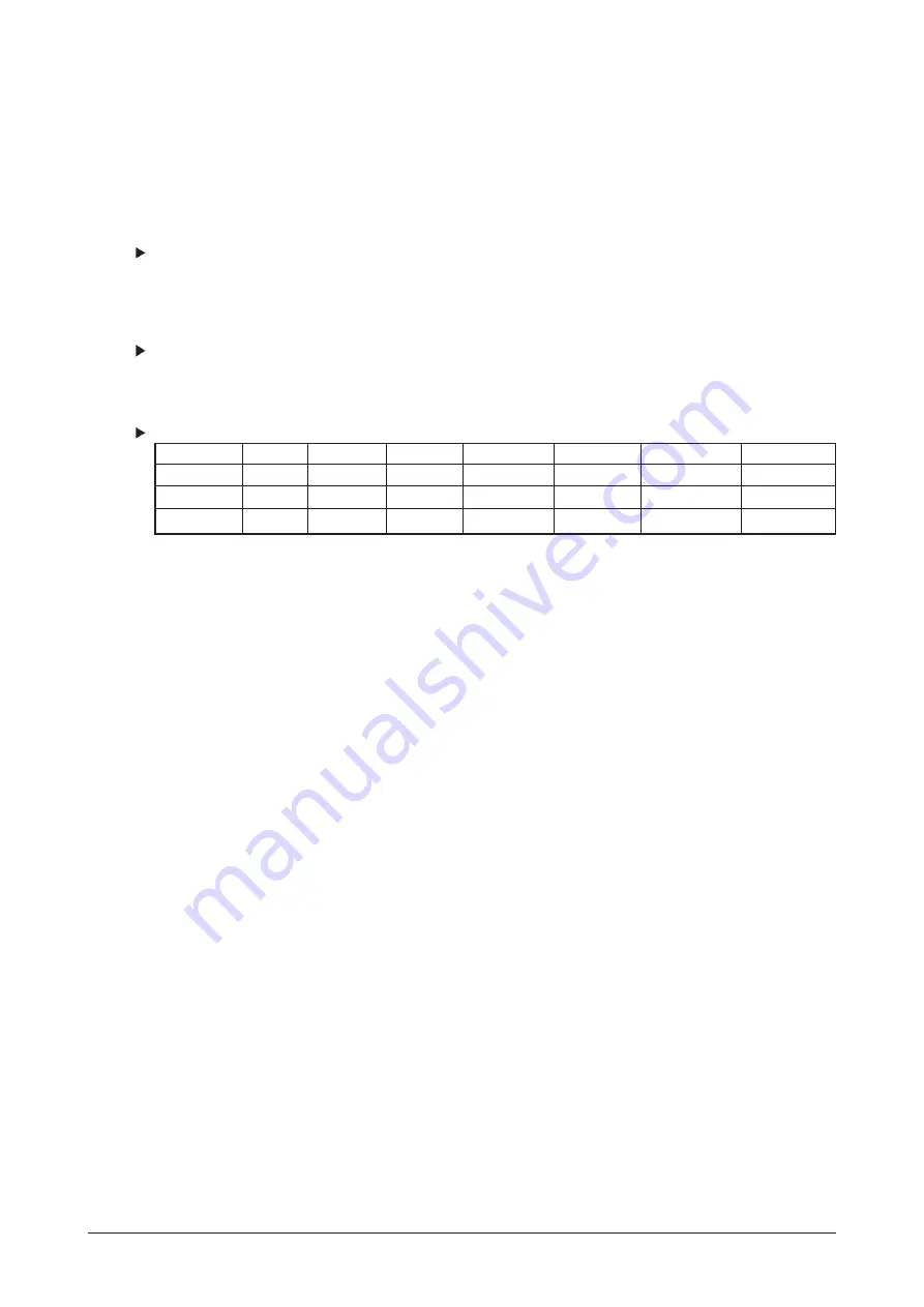
sure that it has been set to a compatible video output mode as shown in the table below.
Failure to observe this may result in picture distortion, image breakup or no picture.
Supported modes for HDMI/DVI and COMPONENT
- Do not attempt to connect the HDMI/DVI connector to a PC or Laptop Graphics Card.
(This will result in a blank screen being displayed)
3.
Connecting External A/V Devices (AV IN 1)
- Connect RCA cable to an appropriate external A/V device such as VCR, DVD or Camcorder.
- Connect RCA audio cables to "R - AUDIO - L" on the rear of your set and the other ends to corresponding audio
out connectors on the A/V device.
5.
Connecting External A/V Devices
- Connect RCA or S-VIDEO cable to an appropriate external A/V device such as VCR, DVD or Camcorder.
- Connect RCA audio cables to "R - AUDIO - L" on the rear of your set and the other ends to corresponding audio
out connectors on the A/V device.
- Headphone may be connected to the headphone output (
4
) on the rear of your set. While the headphone is
connected, the sound from the built-in speakers will be disabled.
6.
SERVICE
- Service connection for qualified service engineer.
7.
Connecting AUDIO
- Connect RCA audio cables to "R - AUDIO - L" on the rear of your set and the other ends to corresponding audio
in connectors on the Amplifier or DVD Home Theater.
8.
Connecting Computer
- Connect the D- Sub cable (optional) to "PC (PC IN)" on the rear of your set and the other end to the Video Card
of your computer.
- Connect the stereo audio cable (optional) to "AUDIO (PC IN)" on the rear of your set and the other end to "Audio
Out" of the sound card on your computer.
9.
Connecting Component Devices (DTV/DVD)
- Connect component video cables (optional) to component connector ("P
R
", "P
B
", "Y") on the rear of your set and
the other ends to corresponding component video out connectors on the DTV or DVD.
- If you wish to connect both the Set-Top Box and DTV (or DVD), you should connect the Set-Top Box to the DTV
(or DVD) and connect the DTV (or DVD) to component connector ("P
R
", "P
B
", "Y") on your set.
- The PR, PB and Y connectors on your component devices (DTV or DVD) are sometimes labeled Y, B-Y and R-Y
or Y, Cb and Cr.
- Connect RCA audio cables (optional) to "R - AUDIO - L" on the rear of your set and the other ends to
corresponding audio out connectors on the DTV or DVD.
- This LCD TV displays its optimum picture resolution in 1080p mode.
- This LCD TV displays its maximum picture resolution in 1080p mode.
10. Kensington Lock
- The Kensington lock (optional) is a device used to physically fix the system when used in a public place.
- If you want to use a locking device, contact the dealer where you purchased the TV.
- The place of the Kensington Lock may be different depending on its model.
480i
480p
576i
576p
720p
1080i
1080p
50Hz
X
X
X
O
O
O
X
60Hz
X
O
X
X
O
O
O
Component
O
O
O
O
O
O
O
Содержание LA40F71BX
Страница 3: ...Contents...
Страница 4: ...Contents...
Страница 25: ...11 Disassembly and Reassembly 11 10 Memo...
Страница 29: ...4 Troubleshooting 4 4 WAVEFORMS 1...
Страница 31: ...4 Troubleshooting 4 6 2...
Страница 33: ...4 Troubleshooting 4 8 WAVEFORMS 4 3...
Страница 35: ...4 Troubleshooting 4 10 WAVEFORMS 5...
Страница 37: ...4 Troubleshooting 4 12 6 WAVEFORMS...
Страница 39: ...4 Troubleshooting 4 14 WAVEFORMS 7...
Страница 50: ...7 Block Diagrams 7 1 7 Block Diagram This Document can not be used without Samsung s authorization...
Страница 51: ...7 Block Diagrams 7 2 Memo...
Страница 52: ...12 PCB Diagram 12 1 12 PCB Diagram 12 1 Main PCB Layout 12 1 1 Main PCB Layout 40 46...
Страница 53: ...12 PCB Diagram 12 2 12 1 2 Main PCB Layout 52...
Страница 54: ...12 PCB Diagram 12 3 12 2 IP Board Diagram 40...
Страница 55: ...12 PCB Diagram 12 4 12 3 IP BOARD Diagram 46...
Страница 56: ...8 1 8 Wiring Diagrams 8 Wiring Diagram 8 1 Wiring Diagram...
Страница 69: ...8 Wiring Diagrams 8 14 Memo...
Страница 146: ...13 Circuit Descriptions 13 3 13 2 Main Block...
Страница 147: ...13 Circuit Descriptions 13 4 13 3 IP Board...
Страница 153: ...Memo 10 Operating Instructions and Installation 10 6...
Страница 161: ...14 Reference Infomation 14 8 14 3 2 Supported Modes 1...
Страница 162: ...14 Reference Infomation 14 9 14 3 3 Supported Modes 2...
Страница 163: ...14 Reference Infomation 14 10 14 3 4 Supported Modes 3...
Страница 173: ...Memo 1 Precautions 1 4...
Страница 175: ...9 Schematic Diagrams 9 2 9 2 Input Output Schematic Diagram...
Страница 176: ...9 Schematic Diagrams 9 3 9 3 Input Output Schematic Diagram...
Страница 177: ...9 Schematic Diagrams 9 4 9 4 Micom Schematic Diagram...
Страница 178: ...9 Schematic Diagrams 9 5 9 5 SVP LX Schematic Diagram 9 5 1 SVP LX Schematic Diagram 40 46...
Страница 179: ...9 Schematic Diagrams 9 6 9 5 2 SVP LX Schematic Diagram 52...
Страница 180: ...9 Schematic Diagrams 9 7 9 6 Application Schematic Diagram...
Страница 181: ...9 Schematic Diagrams 9 8 9 7 FRCH 100Hz LVDS Schematic Diagram...


