


4-1
Chapter
4
Using the InfoRanger
This chapter explains features of the LEDs and the connectors of the InfoRanger.
Front View
There are 4 LED indicators lights on the front side of the InfoRanger.
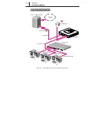
Figure 4-1 Front view of the InfoRanger
When you connect the power adapter to the InfoRanger, a green light is on
LED first, and the InfoRanger processes Self diagnosis
Î
Initialization for
receiving
Î
Initialization for sending
Î
Registering modem and
Authentificating services. While these processes are running, the RCV LED
and SND LED blinks. When this process is complete and the InfoRanger
operates normally, the LED, RCV LED, and SND LED light and remain
green, and PC LED starts blinking. After you connect the Ethernet cable to
the Ethernet port of InfoRanger, the PC LED also turns on steady green.
Reset switch
PWR LED
RCV LED
SND LED
PC LED
MSG LED
Содержание InfoRanger SCM-140U
Страница 11: ...xii This page is left blank intentionally ...
Страница 12: ......
Страница 17: ......
Страница 27: ...2 10 Chapter 2 Prior to Installing This page is left blank intentionally ...
Страница 28: ......
Страница 43: ......
Страница 49: ......
Страница 52: ......
Страница 55: ......
Страница 60: ......


