iDCS 100
INSTALLATION
TECHNICAL MANUAL
PART 6 JUNE 2002
6.2
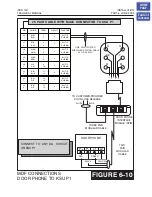
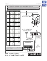
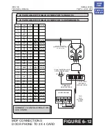
When a customer-provided electric door release is installed, cross-connect the
corresponding door release contacts on the DPIM to the door lock mechanism
. Use
to program the duration of the contact
closure as required.
See the user guides for door lock release operation
release contacts on the DPIM are to be used for low voltage relay control only. The
contacts are rated at 24 VDC-1 amp.
WARNING:
Do not attempt to connect commercial AC power to these contacts.
6.6 ISDN BRI STATIONS
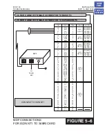
The iDCS 100 uses an S/T type interface so if the BRI station equipment requires a U
type circuit then an NT1 must be connected between the iDCS 100 and the station
equipment. This will convert the circuit from the S/T type 4 wire interface provided by
the iDCS 100 to the U type 2 wire interface required by the station equipment. In this
case the maximum distance of the BRI station equipment from the iDCS 100 is
determined by the specifications of the NT1.
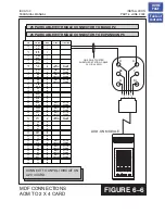
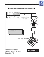
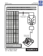
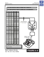
Using two pair twisted #24 AWG or #26 AWG jumper wire cross-connect any BRI port
to the BRI station equipment (or NT1),
For information regarding the programming of a BRI circuit please see the Special
Applications part of the Programming section of this manual.
6.7A WALL-MOUNTING KEYSETS
DCS keysets come equipped with a reversible base wedge. To wall-mount a keyset,
remove the wedge from the keyset and remove the directory tray from the wedge.
Mount the wedge to the wall using one of the methods below
Use screw holes 1 and 2 to attach the base wedge to a standard electrical outlet box.
OR
Use screw holes 1 and 3 to attach to a standard telephone wall-mount plate with
locking pins. This method can cause the keyset to wobble as the keyset feet do not fit
securely to the mounting surface.
OR
Use screw holes 4 and 5 if you are mounting on dry wall with a hole in the middle for
cable access.
HOME
PAGE
Table of
Contents
Содержание iDCS 100
Страница 31: ...FIGURE 3 4 2 SLI CARD iDCS 100 INSTALLATION TECHNICAL MANUAL PART 3 JUNE 2002 HOME PAGE Table of Contents ...
Страница 37: ...S4BRI CARD iDCS 100 INSTALLATION TECHNICAL MANUAL PART 3 JUNE 2002 FIGURE 3 10 HOME PAGE Table of Contents ...
Страница 41: ...MODEM CARD iDCS 100 INSTALLATION TECHNICAL MANUAL PART 3 JUNE 2002 FIGURE 3 14 HOME PAGE Table of Contents ...
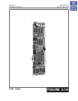
Страница 43: ...ITMC CARD iDCS 100 INSTALLATION TECHNICAL MANUAL PART 3 JUNE 2002 FIGURE 3 16 HOME PAGE Table of Contents ...

