Alignment and Adjustments
Samsung Electronics
3-11
3-5 Beam Alignment
PRECAUTION
1. Input a crosshatch and dot pattern.
2. Select the ÒSTANDARDÓ video mode.
3. Warm up the TV for at least 10 minutes.
4. Connect an audio oscillator to the pin jig between GT23 (located on the deflection PCB) and GND.
5. Determine the ZERO-magnet area (using the beam-alignment CY)
6. Check the squarewave at the point where the focus is misalingned (Use an audio oscillator).
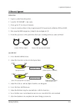
ADJUSTMENT
1. Cover the Red and Blue lenses.
2. Adjust the Green lens as shown in the figures below
3. Adjust the G-Focus until any light around the core disappears.
4. Cover the Green and Blue lenses.
5. Adjust the Red lens using the same method as with the Green lens.
6. Note: The Blue lens is not adjusted because its focus varies little (VM-coil is installed).
7. After the adjustments are completed, disconnect the jig pin connector.
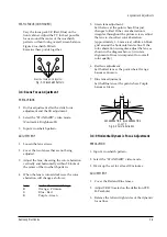
(Creation of CPM Zero Magnet)
(Creation of the 2-pole/4-pole zero magnets)
G-FOCUS
CORE
(Varying G-Focus Pack)
Varying the 2-pole of VM
(Positioning the Core in the Center)
Varying the 4-pole of VM
CORE
G-FOCUS
(When VM 2-Pole Adjustment is completed)
(Adjust until the light around
the core becomes circle)
Содержание HCH551WX
Страница 2: ...ELECTRONICS Samsung Electronics Co Ltd NOV 1998 Printed in Korea 3APT52A 5501 ...
Страница 23: ...MEMO 3 16 Samsung Electronics ...
Страница 62: ...8 2 Samsung Electronics MEMO ...
Страница 67: ...Schematic Diagrams Samsung Electronics 9 5 9 5 3DCOMB1 Power Line Signal Line ...
Страница 68: ...Schematic Diagrams 9 6 Samsung Electronics 9 6 IF_MODULE Power Line Signal Line ...
Страница 73: ...Schematic Diagrams Samsung Electronics 9 11 9 11 CONTROL SUB Power Line ...

