CONNECTIONS
15
14
MIXED AUDIO OUT
R1
R2
L1
R
L
L2
ANALOG AUDIO OUT
R FRONT L
R SURROUND L
CENTER
S/W
OPTICAL
COAXIAL
OPTICAL
COAXIAL
DIGITAL AUDIO OUT
C
hoosing a Connection (ContÕd)
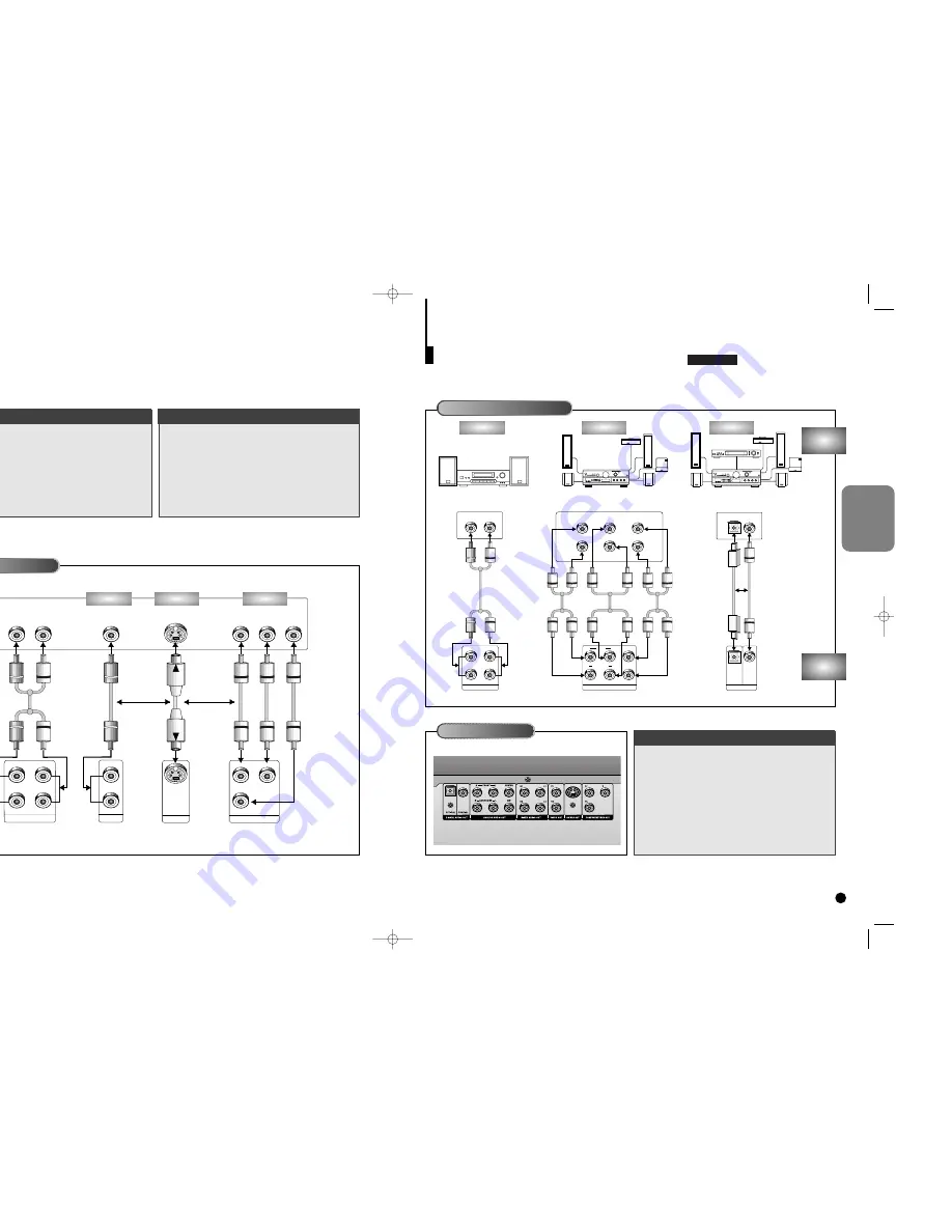
Connecting to an Audio System
AUDIO
SYSTEM
DVD
PLAYER
Connecting to an Audio System
Rear Panel
• Method 1
DVD 2ch Stereo Amplifier or
Dolby Pro Logic Decoder
• Method 2
DVD Amplifier with 5.1ch
Analog Input Jacks
• Method 3
DVD Amplifier with Dolby
Digital Decoder/DTS Decoder
Method 1
Method 2
Method 3
Mixed Audio Out
Analog Audio Out
Audio Input Jacks
Audio Input Jacks
5.1ch Analog Amplifier
Dolby Digital Decoder
Digital Audio Input Jacks
2ch Amplifier
Digital Audio Out
Front (RH)
Rear (RH)
Front (LH)
Rear (LH)
Center
Subwoofer
OR
C
hoosing a Connection
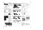
The following show examples of connections commonly used to connect the DVD player with a TV and other
components.
Before Connecting the DVD Player
Connecting to a TV (For Video)
MIXED AUDIO OUT
R1
R2
L1
R
L
L2
COMPONENT VIDEO OUT
Y
Y
Pr
Pr
Pb
Pb
VIDEO OUT
S-VIDEO OUT
V1
V2
TV
DVD
PLAYER
Connecting to a TV
• Method 1
DVD TV with Video Input Jack
• Method 2
DVD TV with S-Video Input Jack
• Method 3
DVD TV with Component Video Jacks
• Always turn off the DVD player, TV, and other com-
ponents before you connect or disconnect any
cables.
• Refer to owner’s manual of the components you
are connecting for more information on those par-
ticular components.
TV (Normal, Widescreen, Projection, etc..)
Audio Input Jacks
Good
picture
Basic Audio
OR
OR
AV Cable
(included)
S-Video
Cable
(included)
Video Cables
(not included)
Better
picture
Best picture
Video Input Jack
S-Video Jack
Component Video Jacks
Method 1
Method 2
Method 3
DVD-C700
C700/C600_Can./USA 9/1/00 12:22 PM Page 14


