Circuit Descriptions
Samsung Electronics
6-5
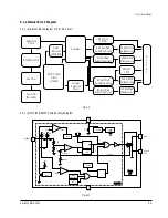
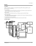
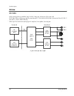
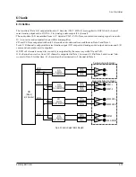
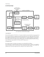
6-1-3 Internal Block Diagram
6-1-3 (a) Internal Block Diagram of S.M.P.S. Circuit
Smoothing
Circuit
Rectified Circuit
Line Filter
Power IN
(85~265V)
Noise
Removal
(SNUBBER)
PWM Control
Circuit
(1L0380)
Converter
Voltage
Detection
Circuit
FLT Driving
Circuit
3.3V Rectified
Smoothing Circuit
5V Rectified
Smoothing Circuit
8V Rectified
Smoothing Circuit
-8V Rectified
Smoothing Circuit
3.3V Rectified
VoltageCircuit
5V Rectified
VoltageCircuit (x2)
Motor 8V
1 Port
8V Rectified
VoltageCircuit
-8V Rectified
VoltageCircuit
O
U
T
P
U
T
Fig. 6-9
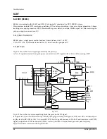
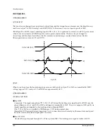
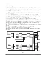
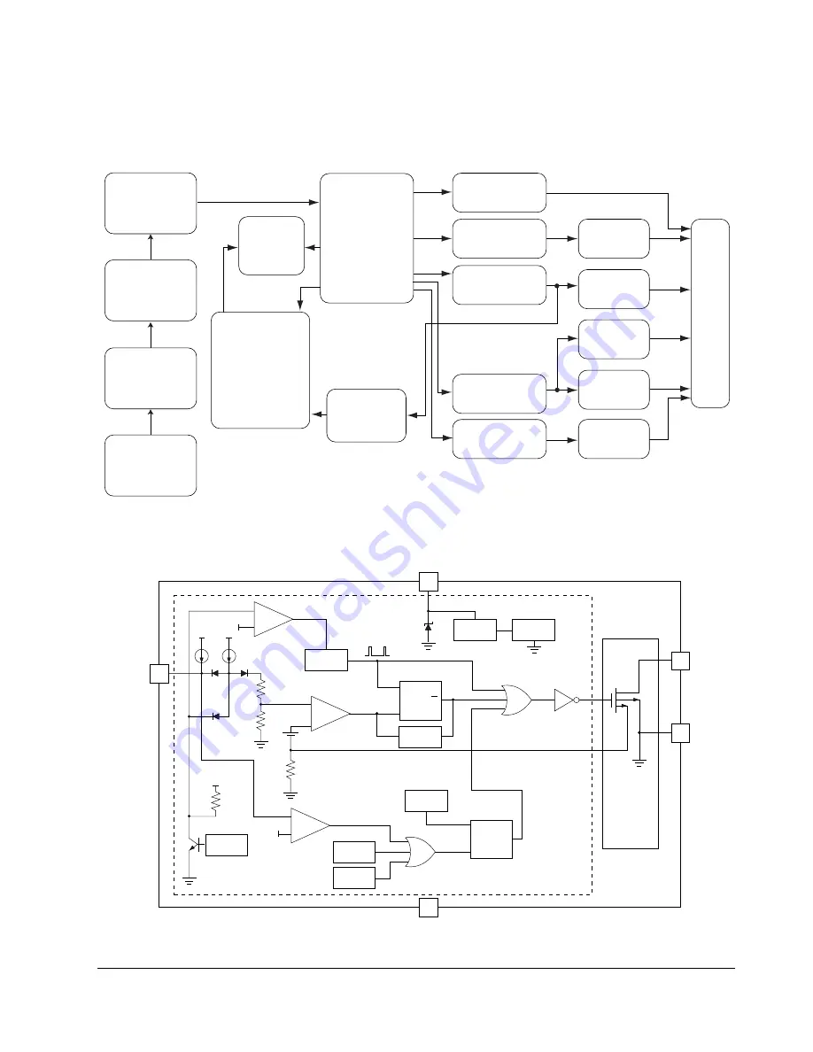
6-1-3 (b) PIC1 (STR-G6153T) Internal Block Diagram
Voltage
Ref.
UVLO
V c c
Drain
Source
GND
S e n s e
S
Q
R
S
Q
R
OSC.
Vck
32V
Feedback
LEB
Reset
7.5V
5v
Reset
Thermal
Protection
OVP
2uA
6.3V
Sync.
2.5R
Voffset
Rsense
R
+
_
+
_
1mA
Control IC
Sense
FET
5
O C P
2
4
1
3
Fig. 6-10
Содержание DVD-739
Страница 23: ...Reference Information 2 16 Samsung Electronics MEMO ...
Страница 25: ...Product Specification 3 2 Samsung Electronics MEMO ...
Страница 29: ...Operating Instructions 4 4 Samsung Electronics MEMO ...
Страница 72: ...Samsung Electronics 8 1 8 Exploded View and Parts List 8 1 Cabinet Assembly 8 2 Deck Assembly Page 8 2 8 4 ...
Страница 77: ...Exploded Views and Parts List 8 6 Samsung Electronics MEMO ...
Страница 87: ...Block Diagrams 10 2 Samsung Electronics MEMO ...
Страница 89: ...PCB Diagrams 11 2 Samsung Electronics 11 1 Main COMPONENT SIDE SOLDER SIDE ...
Страница 90: ...PCB Diagrams Samsung Electronics 11 3 11 2 Jack ...
Страница 91: ...PCB Diagrams 11 4 Samsung Electronics 11 5 Deck 11 4 Play 11 3 Power ...
Страница 92: ...Samsung Electronics 12 1 12 Wiring Diagram JACK PCB MAIN PCB DECK PCB PLAY PCB POWER PCB ...
Страница 93: ...Wiring Diagram 12 2 Samsung Electronics MEMO ...
Страница 95: ...Schematic Diagrams 13 2 Samsung Electronics 13 1 S M P S ...
Страница 96: ...Schematic Diagrams Samsung Electronics 13 3 13 2 Main Power Supply ...
Страница 97: ...Schematic Diagrams 13 4 Samsung Electronics 13 3 Main Micom ...
Страница 98: ...Schematic Diagrams Samsung Electronics 13 5 13 4 Servo ...
Страница 99: ...Schematic Diagrams 13 6 Samsung Electronics 13 5 Video Y Output C Output CVBS Output ...
Страница 100: ...Schematic Diagrams Samsung Electronics 13 7 13 6 Audio ...
Страница 101: ...Schematic Diagrams 13 8 Samsung Electronics KCN1 KCN2 13 7 5 1 Channel Audio DVD 929K Only ...
Страница 102: ...Schematic Diagrams Samsung Electronics 13 9 13 8 RF ...
Страница 103: ...Schematic Diagrams 13 10 Samsung Electronics 13 9 ZiVA ...
Страница 104: ...Schematic Diagrams Samsung Electronics 13 11 13 10 DSP ...
Страница 105: ...Schematic Diagrams 13 12 Samsung Electronics CN18 TO KARAOKE KCN3 CN15 TO KEY CON21 13 11 Front Micom VFD Display ...
Страница 107: ...Schematic Diagrams 13 14 Samsung Electronics 13 13 Mute ...
Страница 108: ...Schematic Diagrams Samsung Electronics 13 15 13 14 Karaoke Power ...
Страница 109: ...Schematic Diagrams 13 16 Samsung Electronics 13 15 Play ...
Страница 110: ...Schematic Diagrams Samsung Electronics 13 17 13 16 Deck ...
Страница 111: ...Schematic Diagrams 13 18 Samsung Electronics 13 17 Remote Control ...

