background image

Precautions

Specifications and IC Data

Disassembly and Reassembly

Alignment and Adjustments

Troubleshooting

Exploded View and Parts List

Electrical Part List

Block Diagram

Wiring Diagram

Schematic Diagrams

1.

2.

3.

4.

5.

6.

7.

8.

9.

10.

COLOR TELEVISION RECEIVER

Chassis :

K15D(N) 

Model

:

CT20F3FNT/XAP

SERVICE

Manual

COLOR TELEVISION RECEIVER

CONTENTS

Содержание CXD1334

Страница 1: ...gnment and Adjustments Troubleshooting Exploded View and Parts List Electrical Part List Block Diagram Wiring Diagram Schematic Diagrams 1 2 3 4 5 6 7 8 9 10 COLOR TELEVISION RECEIVER Chassis K15D N M...

Страница 2: ...le brackets metal cabinets screwheads and control shafts The current measured should not exceed 0 5 milliamp Reverse the power plug prongs in the AC outlet and repeat the test Fig 1 1 AC Leakage Test...

Страница 3: ...appear to have overheated or that are otherwise damaged should be replaced with parts that meet the original specifications Always determine the cause of damage or overheat ing and correct any potent...

Страница 4: ...and accessible conductive parts examples metal panels input terminals and earphone jacks 6 Insulation Checking Procedure Disconnect the power cord from the AC source and turn the power switch ON Conn...

Страница 5: ...anti static solder removal device Many solder removal devices are not rated as anti static these can accumulate sufficient electrical charge to damage ESDs 7 Do not remove a replacement ESD from its...

Страница 6: ...Input Impedance Speaker Impedance NTSC NTSC 2 13 14 69 45 75 41 25 42 18 System Band VHF UHF 1 125 CABLE SYSTEM IF Carrier Frequency Picture IF Carrier Sound IF Carrier Color Sub Carrier MODEL CT 14 I...

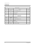
Страница 7: ...24C04 EEPROM PC801S TCET1108 LTV817B PHOTO COUPLER SPM458AN TDA9377 English Spanish French IC201S Philips Philips Philips FIAIR CHILD VERTICAL OUTPUT LA7840 TDA7266M TDA7266S SOUND AMP IC301 IC602 TD...

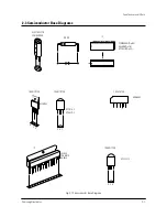
Страница 8: ...Electronics 2 3 ELECTROLYTIC CONDENSER IC DIODE SPM458AN Pin 64 U4468B Pin 16 UPC851B Pin 42 IC TRANSISTOR LA7840 TDA6107Q KA7632 TRANSISTOR TRANSISTOR KSC5802 B C E E B C KSC815 Y KSA539 Y SAW FILTE...

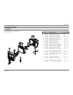
Страница 9: ...C BLK SWR 1 T0081 S N A 1 9 AA64 03007A KNOB CONTROL 14F3 ABS HB G3676 SVM 3012 1 T0022 S N A 1 10 6002 000512 SCREW TAPPING RH 2 M4 L12 ZPC BLK SWR 1 T0081 S N A 1 11 AA96 10007A ASSY SPEAKER 8ohm 3W...

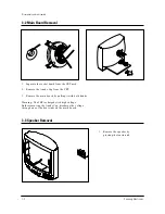
Страница 10: ...eassembly Samsung Electronics 3 1 3 Disassembly and Reassembly 3 1 Back Cover Removal 1 After removing the screws press the tension rib and pull the cabinet backwards 2 To reassemble press the tension...

Страница 11: ...ket board from the CRT neck 2 Remove the Anode Cap from the CRT 3 Remove the main board by pulling it with both hands Warning The FBT is charged with high voltage Before removing the Anode Cap dischar...

Страница 12: ...T to the front cabi net Lift the CRT 3 Caution Because of the high vacuum and large surface area of the picture tube be careful while handling it 1 Always lift the picture tube by grasping it firmly a...

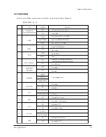
Страница 13: ...the last step 2 If the EEPROM or CRT is replaced and set SC as 20 factory mode 4 2 Factory Service Mode 4 2 1 Procedure for the Adjustment Mode 1 This mode uses the standard remote control The Servic...

Страница 14: ...Pre overshoot Ratio Pre overshoot Window Selection Sound PLL IF AGC Speed Offset IF Demodulator Soft Clipping Level Peak White Limitting Matrix USA Automatic Gain Control Dynamic Skin Tone DVD Bright...

Страница 15: ...ON OFF OFF ON ENGLISH ESPANOL FRENCH PORTU OFF ON AIR STD HRC IRC AIR STD HRC AFN ON OFF ON OFF TV AV TV AV DVD ON OFF 800msec Mute Time Tri norma Unavailable Zenith stereo WITH IN UPC1851B Line stere...

Страница 16: ...uency as specified on the backcover nameplate 7 Do not attempt to connect or disconnect any wires while the TV is turned on Make sure that the power cord is disconnected before replacing any parts 8 T...

Страница 17: ...lloscope probe 2 Input a gray scale pattern Use a pattern gen erator PM5518 3 Use the P mode key on the remote control for the STANDARD picture 4 Adjust the Screen VR on the FBT so that the voltage on...

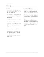
Страница 18: ...m Vertical Green Belt Fig 4 4 1 2 a Set up 1 Warm up the TV for at least 30 minutes in the Aging Mode OSD White This mode is dis played by entering the following sequence DISPLAY FACTORY FACTORY 2 Inp...

Страница 19: ...nd the blue vertical lines in the center area of the screen 5 Turn the both tabs at the same time keeping the angle constant and superimpose the red and blue horizontal line in the center of the scree...

Страница 20: ...that the lion head circle becomes oval 3 Adjust with VA Vertical Amplitude so that the top margin of the picture is 4 Fig 4 7 4 Adjust with VSL Vertical Slope so that the bottom margin of the picture...

Страница 21: ...A 4 0205 001153 GREASE SILICON SC102 JAPAN S N A 4 T0088 1204 001483 IC VERTICAL PROCESSO LA7840 SIP 7P 708MI 4 T0081 6003 000335 SCREW TAPTITE RH 2S M3 L8 ZPC YEL SWR S N A 4 AA62 00046A HEAT SINK P...

Страница 22: ...2001 000449 R CARBON 2 2KOHM 5 1 8W AA TP 1 8X3 2MM 4 R125 2001 000472 R CARBON 2 7KOHM 5 1 8W AA TP 1 8X3 2MM 4 R125 2001 000472 R CARBON 2 7KOHM 5 1 8W AA TP 1 8X3 2MM 4 R125 2001 000472 R CARBON 2...

Страница 23: ...TOR AXIAL 1UH 10 2534 4 L102 2701 000159 INDUCTOR AXIAL 22UH 10 4298 4 L201 2701 000159 INDUCTOR AXIAL 22UH 10 4298 4 L230 2701 000159 INDUCTOR AXIAL 22UH 10 4298 4 L405 2701 000159 INDUCTOR AXIAL 22U...

Страница 24: ...S N A 2 T0511 AA68 02666A MANUAL USERS SPA W P100 G B5 K15D S N A 2 BAG PE AA69 01195A BAG PE CL29A6W8X HDPET0 012 93 4X151 2 S N A ASSY P MATERIAL 1 A PACK AA92 07233B ASSY P MATERIAL CT20F3FX XAX S...

Страница 25: ...4 3 2 1 SOUND R IN GND SOUND R OUT SOUND L OUT VIDEO IN VIDEO OUT SOUND L IN 1 2 3 4 R OUT B OUT G OUT GND B C P V A 9 5 8 7 6 GND IK GND HEAT B OUT 1 0 5 N C O E R E T S 1 0 6 N C 1 0 7 N C 4 3 2 1 L...

Страница 26: ...bnormal Abnormal Abnormal Counect the Power code Check the X tal SDA SCL port of IC201S Check the 33 Pin H Drive of IC201S Check the 122 5V A Line Check the 3 3V A 5V A Line of IC201S Check Replace IC...

Страница 27: ...rmal Abnormal Check RK GK BK Signal Check R G B Signal into CRT PCB Check the resistance of R420 Check IC201S Pin 49 BCL IN Pin50 IK Check IC501 B 180V B Check the Voltage of heater Check CRT and FBT...

Страница 28: ...aker and Wire Check Replace ICS601 Check IC201S TUNER Check Replace IC201S See No Power Check TUNER Replace IC601 Replace Check IC601 Replace FD801S D807 Check IC601 Pin1 2 14 15 Check IC201S Pin28 MI...

Страница 29: ...lectronics Troubleshooting 5 4 Vertical Lines Appear or Screen Normal Normal Abnormal Abnormal Check R304 R305 D301 D302 Check IC201S Check IC201S Pin 21 22 VDN VDP Check IC301 B 16V C 13 5V C Check R...

Страница 30: ...6107 E 2PR OM 24C04 AC KA5Q0740RT KA5Q0765RT S W MULTI REGULATOR 3 3V TO MCU 8V TO MCU I 2C AUDIO A M P TDA7266M S F STEREO SOUND PROCESSOR UPD1851B BT FSV 14A004C VIDEO I 2C IC M C U SP M 458A N 2 3...

Страница 31: ...TP06 TP05 TP04 TP02 TP03 TP01 Schematic Diagrams 10 1 Samsung Electronics 10 Schematic Diagrams 10 1 MAIN 1 4 TP01 TP02 TP03 TP04 TP05 TP06...

Страница 32: ...Schematic Diagrams 10 2 Samsung Electronics 10 2 MAIN 2 4 TP08 TP07 TP11 TP10 TP09 TP07 TP08 TP09 TP10 TP11...

Страница 33: ...Schematic Diagrams 10 3 Samsung Electronics 10 3 MAIN 3 4 TP08 TP07 TP07 TP08 Power Line Signal Line...

Страница 34: ...Schematic Diagrams 10 4 Samsung Electronics 10 4 MAIN 4 4...

Отзывы: