3
.
Installing the Product
English 8/2020. Rev 0.3
79
3.10.6
Module and SMU Signal Cable Connection
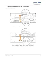
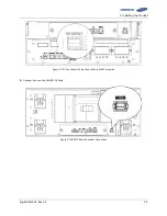
Connect the signal cables for SMU and Module BMS’s for each module.
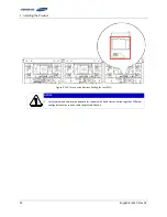
NOTICE
Use the proper signal cables as specified by the part numbers below.
WARNING
Rack BMS / Module BMS Damage
Do not insert both ends of the signal cable WIRE ASSY MODULE TO MODULE #1 or WIRE ASSY
MODULE TO MODULE #2 into the same Battery Module.
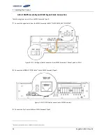
1.
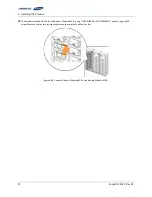
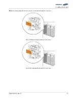
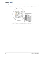
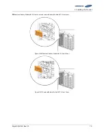
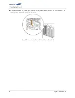
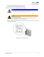
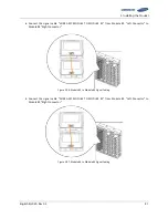
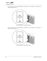
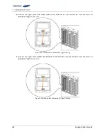
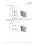
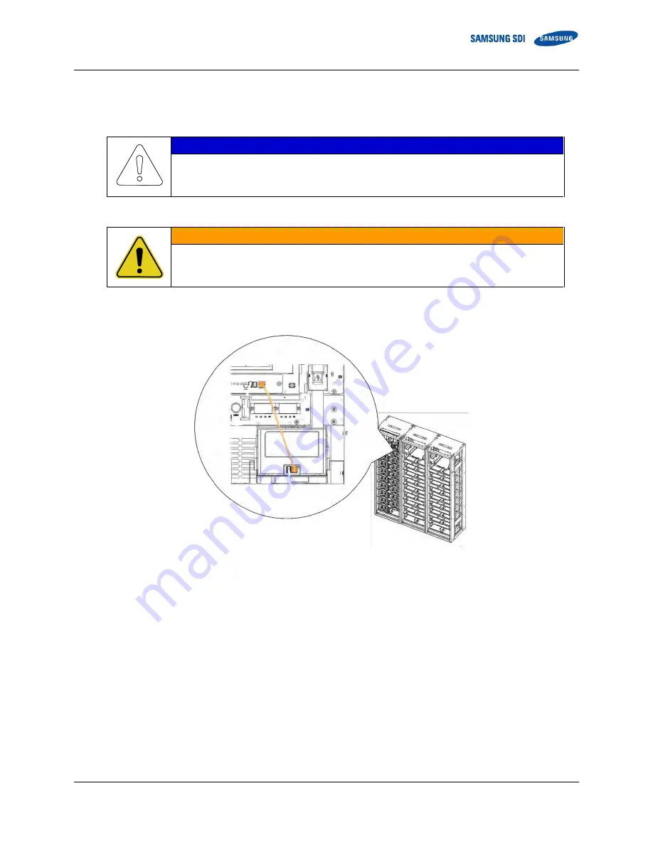
Connect the signal cable “WIRE ASSY RACK TO MODULE” between the SMU “MODULE” connector and
Module #1 “Right Connector”.
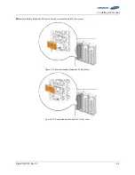
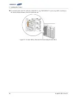
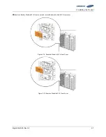
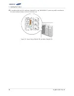
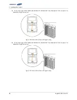
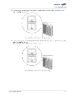
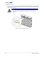
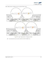
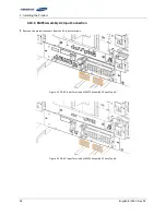
Figure 3-93: SMU to Module #1 Signal Cable
Содержание 9395
Страница 1: ...English 8 2020 Rev 0 3 LIB System for UPS U6A4 Installation Manual 136S ...
Страница 4: ...English 8 2020 Rev 0 3 ...
Страница 10: ...Important Safety Instructions vi English 8 2020 Rev 0 3 ...
Страница 17: ...Table of Contents English 8 2020 Rev 0 3 vii ...
Страница 18: ......
Страница 78: ...3 Installing the Product 60 English 8 2020 Rev 0 3 Figure 3 63 Remove Battery Modules 9 s Front Cover ...
Страница 117: ...3 Installing the Product English 8 2020 Rev 0 3 99 Figure 3 130 AC Input Terminals of SMPS Assembly 1 Phase Type B ...
Страница 126: ...Memo ...
Страница 127: ...Memo ...
Страница 128: ...Memo ...
Страница 129: ...www SamsungSDI com ...

